HP Dv71270us Service Guide - Page 106
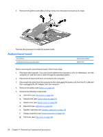
Remove the two Phillips PM2.5×4.0 broad-head screws, that secure the subwoofer to
 |
UPC - 884420712770
View all HP Dv71270us manuals
Add to My Manuals
Save this manual to your list of manuals |
Page 106 highlights
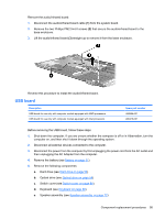
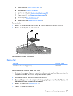
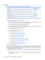
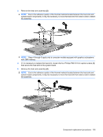
a. Hard drive (see Hard drive on page 56) b. Optical drive (see Optical drive on page 54) c. Switch cover (see Switch cover on page 66) d. Keyboard (see Keyboard on page 68) e. Speaker assembly (see Speaker assembly on page 72) f. Display assembly (see Display assembly on page 73) g. Top cover (see Top cover on page 82) h. System board (see System board on page 91) Remove the subwoofer: 1. Remove the two Phillips PM2.5×4.0 broad-head screws (1) that secure the subwoofer to the base enclosure. NOTE: When removing the subwoofer screws, make note of the location and orientation of the rubber grommets (2). Failure to properly install these grommets can lead to decreased subwoofer performance. 2. Remove the subwoofer (3) from the base enclosure. Reverse this procedure to install the subwoofer. 98 Chapter 4 Removal and replacement procedures
-
 1
1 -
2
-
3
-
4
-
5
-
6
-
7
-
8
-
9
-
10
-
11
-
12
-
13
-
14
-
15
-
16
-
17
-
18
-
19
-
20
-
21
-
22
-
23
-
24
-
25
-
26
-
27
-
28
-
29
-
30
-
31
-
32
-
33
-
34
-
35
-
36
-
37
-
38
-
39
-
40
-
41
-
42
-
43
-
44
-
45
-
46
-
47
-
48
-
49
-
50
-
51
-
52
-
53
-
54
-
55
-
56
-
57
-
58
-
59
-
60
-
61
-
62
-
63
-
64
-
65
-
66
-
67
-
68
-
69
-
70
-
71
-
72
-
73
-
74
-
75
-
76
-
77
-
78
-
79
-
80
-
81
-
82
-
83
-
84
-
85
-
86
-
87
-
88
-
89
-
90
-
91
-
92
-
93
-
94
-
95
-
96
-
97
-
98
-
99
-
100
-
 101
101 -
 102
102 -
 103
103 -
 104
104 -
 105
105 -
 106
106 -
 107
107 -
 108
108 -
 109
109 -
 110
110 -
 111
111 -
112
-
113
-
114
-
115
-
116
-
117
-
118
-
119
-
120
-
121
-
122
-
123
-
124
-
125
-
126
-
127
-
128
-
129
-
130
-
131
-
132
-
133
-
134
-
135
-
136
-
137
-
138
-
139
-
140
-
141
-
142
-
143
-
144
-
145
-
146
-
147
-
148
-
149
-
150
-
151
-
152
-
153
-
154
-
155
-
156
-
157
-
158
-
159
-
160
-
161
-
162
-
163
-
164
-
165
-
166
-
167
-
168
-
169
-
170
-
171
-
172
-
173
-
174
-
175
-
176
-
177
-
178
-
179
-
180
-
181
 |
 |