HP Dv71270us Service Guide - Page 81
Display assembly, Switch cover see
 |
UPC - 884420712770
View all HP Dv71270us manuals
Add to My Manuals
Save this manual to your list of manuals |
Page 81 highlights
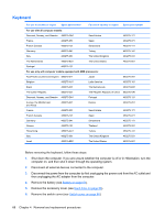
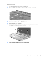
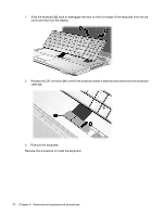
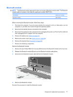
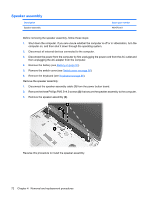
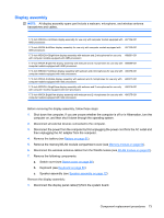
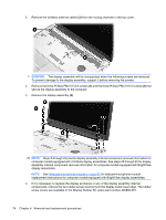
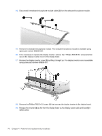
Display assembly NOTE: All display assembly spare part include a webcam, microphone, and wireless antenna transceivers and cables. 17.0-inch WSXGA+ AntiGlare display assembly for use only with computer models equipped with 497104-001 AMD processors 17.0-inch WXGA AntiGlare display assembly for use only with computer models equipped with 497103-001 AMD processors 17.0-inch WSXGA+ BrightView display assembly with webcam and 2 microphones for use only 488881-001 with computer models equipped with AMD processors 17.0-inch WXGA BrightView display assembly with webcam and 2 microphones for use only with 488880-001 computer models equipped with AMD processors 17.0-inch WSXGA+ AntiGlare display assembly with webcam and 2 microphones for use only with 480378-001 computer models equipped with Intel processors 17.0-inch WXGA AntiGlare display assembly with webcam and 2 microphones for use only with 480377-001 computer models equipped with Intel processors 17.0-inch WSXGA+ BrightView display assembly with webcam and 2 microphones for use only 480376-001 with computer models equipped with Intel processors 17.0-inch WXGA BrightView display assembly with webcam and 2 microphones for use only with 480375-001 computer models equipped with Intel processors Before removing the display assembly, follow these steps: 1. Shut down the computer. If you are unsure whether the computer is off or in Hibernation, turn the computer on, and then shut it down through the operating system. 2. Disconnect all external devices connected to the computer. 3. Disconnect the power from the computer by first unplugging the power cord from the AC outlet and then unplugging the AC adapter from the computer. 4. Remove the battery (see Battery on page 51). 5. Remove the memory/WLAN module compartment cover (see Memory module on page 64). 6. Disconnect the wireless antenna cables from the WLAN module (see WLAN module on page 61). 7. Remove the following components: a. Switch cover (see Switch cover on page 66) b. Keyboard (see Keyboard on page 68) c. Speaker assembly (see Speaker assembly on page 72) Remove the display assembly: 1. Disconnect the display panel cable (1) from the system board. Component replacement procedures 73
-
 1
1 -
2
-
3
-
4
-
5
-
6
-
7
-
8
-
9
-
10
-
11
-
12
-
13
-
14
-
15
-
16
-
17
-
18
-
19
-
20
-
21
-
22
-
23
-
24
-
25
-
26
-
27
-
28
-
29
-
30
-
31
-
32
-
33
-
34
-
35
-
36
-
37
-
38
-
39
-
40
-
41
-
42
-
43
-
44
-
45
-
46
-
47
-
48
-
49
-
50
-
51
-
52
-
53
-
54
-
55
-
56
-
57
-
58
-
59
-
60
-
61
-
62
-
63
-
64
-
65
-
66
-
67
-
68
-
69
-
70
-
71
-
72
-
73
-
74
-
75
-
 76
76 -
 77
77 -
 78
78 -
 79
79 -
 80
80 -
 81
81 -
 82
82 -
 83
83 -
 84
84 -
 85
85 -
 86
86 -
87
-
88
-
89
-
90
-
91
-
92
-
93
-
94
-
95
-
96
-
97
-
98
-
99
-
100
-
101
-
102
-
103
-
104
-
105
-
106
-
107
-
108
-
109
-
110
-
111
-
112
-
113
-
114
-
115
-
116
-
117
-
118
-
119
-
120
-
121
-
122
-
123
-
124
-
125
-
126
-
127
-
128
-
129
-
130
-
131
-
132
-
133
-
134
-
135
-
136
-
137
-
138
-
139
-
140
-
141
-
142
-
143
-
144
-
145
-
146
-
147
-
148
-
149
-
150
-
151
-
152
-
153
-
154
-
155
-
156
-
157
-
158
-
159
-
160
-
161
-
162
-
163
-
164
-
165
-
166
-
167
-
168
-
169
-
170
-
171
-
172
-
173
-
174
-
175
-
176
-
177
-
178
-
179
-
180
-
181
 |
 |