HP Dv71270us Service Guide - Page 104
Fan, Exhaust air is displaced through the ventilation grill located on the left side of the computer.
 |
UPC - 884420712770
View all HP Dv71270us manuals
Add to My Manuals
Save this manual to your list of manuals |
Page 104 highlights
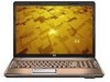
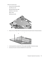
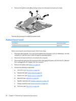
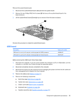
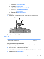
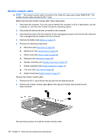
f. Display assembly (see Display assembly on page 73) g. Top cover (see Top cover on page 82) Remove the USB board: 1. Disconnect the USB board cable (1) from the system board. 2. Remove the Phillips PM2.5×4.0 screw (2) that secures the USB board to the base enclosure. 3. Remove the USB board (3) from the base enclosure. Fan Reverse this procedure to install the USB board. Description For use only with computer models equipped with AMD processors For use only with computer models equipped with Intel processors Spare part number 488885-001 480481-001 NOTE: To properly ventilate the computer, allow at least a 7.6-cm (3-inch) clearance on the right side and rear panel of the computer. The computer uses an electric fan for ventilation. The fan is controlled by a temperature sensor and is designed to turn on automatically when high temperature conditions exist. These conditions are affected by high external temperatures, system power consumption, power management/battery conservation configurations, battery fast charging, and software applications. Exhaust air is displaced through the ventilation grill located on the left side of the computer. Before removing the fan, follow these steps: 1. Shut down the computer. If you are unsure whether the computer is off or in Hibernation, turn the computer on, and then shut it down through the operating system. 2. Disconnect all external devices connected to the computer. 3. Disconnect the power from the computer by first unplugging the power cord from the AC outlet and then unplugging the AC Adapter from the computer. 4. Remove the battery (see Battery on page 51). 5. Remove the following components: a. Hard drive (see Hard drive on page 56) b. Optical drive (see Optical drive on page 54) 96 Chapter 4 Removal and replacement procedures
-
 1
1 -
2
-
3
-
4
-
5
-
6
-
7
-
8
-
9
-
10
-
11
-
12
-
13
-
14
-
15
-
16
-
17
-
18
-
19
-
20
-
21
-
22
-
23
-
24
-
25
-
26
-
27
-
28
-
29
-
30
-
31
-
32
-
33
-
34
-
35
-
36
-
37
-
38
-
39
-
40
-
41
-
42
-
43
-
44
-
45
-
46
-
47
-
48
-
49
-
50
-
51
-
52
-
53
-
54
-
55
-
56
-
57
-
58
-
59
-
60
-
61
-
62
-
63
-
64
-
65
-
66
-
67
-
68
-
69
-
70
-
71
-
72
-
73
-
74
-
75
-
76
-
77
-
78
-
79
-
80
-
81
-
82
-
83
-
84
-
85
-
86
-
87
-
88
-
89
-
90
-
91
-
92
-
93
-
94
-
95
-
96
-
97
-
98
-
 99
99 -
 100
100 -
 101
101 -
 102
102 -
 103
103 -
 104
104 -
 105
105 -
 106
106 -
 107
107 -
 108
108 -
 109
109 -
110
-
111
-
112
-
113
-
114
-
115
-
116
-
117
-
118
-
119
-
120
-
121
-
122
-
123
-
124
-
125
-
126
-
127
-
128
-
129
-
130
-
131
-
132
-
133
-
134
-
135
-
136
-
137
-
138
-
139
-
140
-
141
-
142
-
143
-
144
-
145
-
146
-
147
-
148
-
149
-
150
-
151
-
152
-
153
-
154
-
155
-
156
-
157
-
158
-
159
-
160
-
161
-
162
-
163
-
164
-
165
-
166
-
167
-
168
-
169
-
170
-
171
-
172
-
173
-
174
-
175
-
176
-
177
-
178
-
179
-
180
-
181
 |
 |