HP Dv71270us Service Guide - Page 63
that secure the optical drive bracket to the, Remove the two Phillips PM2.0×4.0 screws
 |
UPC - 884420712770
View all HP Dv71270us manuals
Add to My Manuals
Save this manual to your list of manuals |
Page 63 highlights
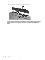
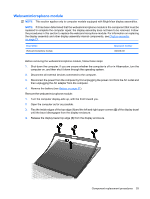
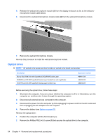
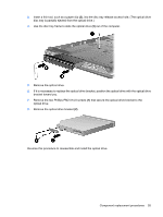
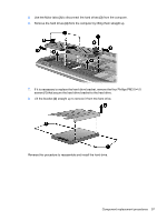
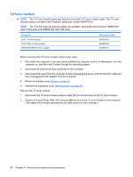
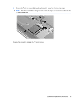
3. Insert a thin tool, such as a paper clip (2), into the disc tray release access hole. (The optical drive disc tray is partially ejected from the optical drive.) 4. Use the disc tray frame to slide the optical drive (3) out of the computer. 5. Remove the optical drive. 6. If it is necessary to replace the optical drive bracket, position the optical drive with the optical drive bracket toward you. 7. Remove the two Phillips PM2.0×4.0 screws (1) that secure the optical drive bracket to the optical drive. 8. Remove the optical drive bracket (2). Reverse this procedure to reassemble and install the optical drive. Component replacement procedures 55
-
 1
1 -
2
-
3
-
4
-
5
-
6
-
7
-
8
-
9
-
10
-
11
-
12
-
13
-
14
-
15
-
16
-
17
-
18
-
19
-
20
-
21
-
22
-
23
-
24
-
25
-
26
-
27
-
28
-
29
-
30
-
31
-
32
-
33
-
34
-
35
-
36
-
37
-
38
-
39
-
40
-
41
-
42
-
43
-
44
-
45
-
46
-
47
-
48
-
49
-
50
-
51
-
52
-
53
-
54
-
55
-
56
-
57
-
 58
58 -
 59
59 -
 60
60 -
 61
61 -
 62
62 -
 63
63 -
 64
64 -
 65
65 -
 66
66 -
 67
67 -
 68
68 -
69
-
70
-
71
-
72
-
73
-
74
-
75
-
76
-
77
-
78
-
79
-
80
-
81
-
82
-
83
-
84
-
85
-
86
-
87
-
88
-
89
-
90
-
91
-
92
-
93
-
94
-
95
-
96
-
97
-
98
-
99
-
100
-
101
-
102
-
103
-
104
-
105
-
106
-
107
-
108
-
109
-
110
-
111
-
112
-
113
-
114
-
115
-
116
-
117
-
118
-
119
-
120
-
121
-
122
-
123
-
124
-
125
-
126
-
127
-
128
-
129
-
130
-
131
-
132
-
133
-
134
-
135
-
136
-
137
-
138
-
139
-
140
-
141
-
142
-
143
-
144
-
145
-
146
-
147
-
148
-
149
-
150
-
151
-
152
-
153
-
154
-
155
-
156
-
157
-
158
-
159
-
160
-
161
-
162
-
163
-
164
-
165
-
166
-
167
-
168
-
169
-
170
-
171
-
172
-
173
-
174
-
175
-
176
-
177
-
178
-
179
-
180
-
181
 |
 |
3.
Insert a thin tool, such as a paper clip
(2)
, into the disc tray release access hole. (The optical drive
disc tray is partially ejected from the optical drive.)
4.
Use the disc tray frame to slide the optical drive
(3)
out of the computer.
5.
Remove the optical drive.
6.
If it is necessary to replace the optical drive bracket, position the optical drive with the optical drive
bracket toward you.
7.
Remove the two Phillips PM2.0×4.0 screws
(1)
that secure the optical drive bracket to the
optical drive.
8.
Remove the optical drive bracket
(2)
.
Reverse this procedure to reassemble and install the optical drive.
Component replacement procedures
55