HP ENVY dv6-7213nr HP ENVY dv6 Notebook PC Maintenance and Service Guide IMPOR - Page 100
routing channel built into the base enclosure., from the clips
 |
View all HP ENVY dv6-7213nr manuals
Add to My Manuals
Save this manual to your list of manuals |
Page 100 highlights
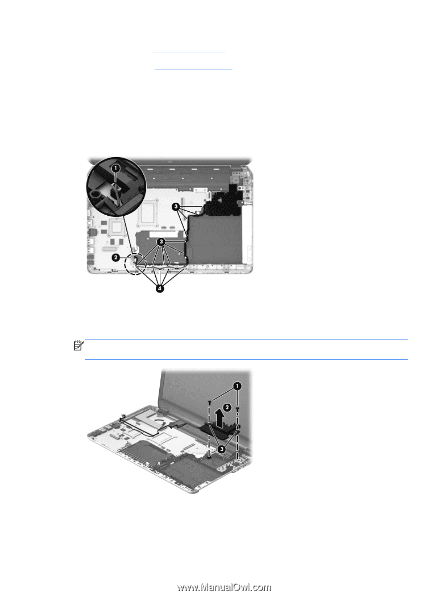
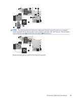
d. Top cover (see Top cover on page 66) e. USB board (see USB board on page 90) Remove the subwoofer: 1. Disconnect the subwoofer cable (1) from the bottom of the system board. 2. Disconnect the top speakers passthrough cable (2) from the system board. 3. Release the subwoofer cable (3) and the top speakers passthrough cable (4) from the clips and routing channel built into the base enclosure. 4. Remove the two Phillips PM2.5×10.0 screws (1) that secure the subwoofer to the base enclosure. 5. Remove the subwoofer (2). NOTE: The subwoofer includes two rubber isolators that are installed in the screw holes (3). These isolators are crucial to the performance of the subwoofer. Reverse this procedure to install the subwoofer. 92 Chapter 4 Removal and replacement procedures
-
 1
1 -
2
-
3
-
4
-
5
-
6
-
7
-
8
-
9
-
10
-
11
-
12
-
13
-
14
-
15
-
16
-
17
-
18
-
19
-
20
-
21
-
22
-
23
-
24
-
25
-
26
-
27
-
28
-
29
-
30
-
31
-
32
-
33
-
34
-
35
-
36
-
37
-
38
-
39
-
40
-
41
-
42
-
43
-
44
-
45
-
46
-
47
-
48
-
49
-
50
-
51
-
52
-
53
-
54
-
55
-
56
-
57
-
58
-
59
-
60
-
61
-
62
-
63
-
64
-
65
-
66
-
67
-
68
-
69
-
70
-
71
-
72
-
73
-
74
-
75
-
76
-
77
-
78
-
79
-
80
-
81
-
82
-
83
-
84
-
85
-
86
-
87
-
88
-
89
-
90
-
91
-
92
-
93
-
94
-
 95
95 -
 96
96 -
 97
97 -
 98
98 -
 99
99 -
 100
100 -
 101
101 -
 102
102 -
 103
103 -
 104
104 -
 105
105 -
106
-
107
-
108
-
109
-
110
-
111
-
112
-
113
-
114
-
115
-
116
-
117
-
118
-
119
-
120
-
121
-
122
-
123
-
124
-
125
-
126
-
127
-
128
-
129
-
130
 |
 |