HP ENVY dv6-7213nr HP ENVY dv6 Notebook PC Maintenance and Service Guide IMPOR - Page 91
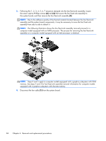
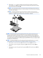
Steps 2 and 3 apply to computer models equipped with a graphics subsystem
 |
View all HP ENVY dv6-7213nr manuals
Add to My Manuals
Save this manual to your list of manuals |
Page 91 highlights
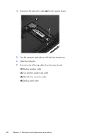
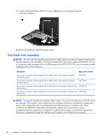
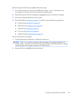
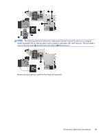
Before removing the fan/heat sink assembly, follow these steps: 1. Turn off the computer. If you are unsure whether the computer is off or in Hibernation, turn the computer on, and then shut it down through the operating system. 2. Disconnect the power from the computer by unplugging the power cord from the computer. 3. Disconnect all external devices from the computer. 4. Remove the battery (see Battery on page 51), and then remove the following components: a. Hard drive (see Hard drive on page 52) b. Optical drive (see Optical drive on page 59) c. Keyboard (see Keyboard on page 61) d. Top cover (see Top cover on page 66) e. System board (see System board on page 77) Remove the fan/heat sink assembly: 1. Turn the system board upside down, with the front toward you. NOTE: Steps 2 and 3 apply to computer models equipped with a graphics subsystem with discrete memory. See steps 4 and 5 for fan/heat sink assembly removal information for computer models equipped with a graphics subsystem with UMA memory. 2. Disconnect the fan cable (1) from the system board. Component replacement procedures 83
-
 1
1 -
2
-
3
-
4
-
5
-
6
-
7
-
8
-
9
-
10
-
11
-
12
-
13
-
14
-
15
-
16
-
17
-
18
-
19
-
20
-
21
-
22
-
23
-
24
-
25
-
26
-
27
-
28
-
29
-
30
-
31
-
32
-
33
-
34
-
35
-
36
-
37
-
38
-
39
-
40
-
41
-
42
-
43
-
44
-
45
-
46
-
47
-
48
-
49
-
50
-
51
-
52
-
53
-
54
-
55
-
56
-
57
-
58
-
59
-
60
-
61
-
62
-
63
-
64
-
65
-
66
-
67
-
68
-
69
-
70
-
71
-
72
-
73
-
74
-
75
-
76
-
77
-
78
-
79
-
80
-
81
-
82
-
83
-
84
-
85
-
 86
86 -
 87
87 -
 88
88 -
 89
89 -
 90
90 -
 91
91 -
 92
92 -
 93
93 -
 94
94 -
 95
95 -
 96
96 -
97
-
98
-
99
-
100
-
101
-
102
-
103
-
104
-
105
-
106
-
107
-
108
-
109
-
110
-
111
-
112
-
113
-
114
-
115
-
116
-
117
-
118
-
119
-
120
-
121
-
122
-
123
-
124
-
125
-
126
-
127
-
128
-
129
-
130
 |
 |
