HP ENVY dv6-7213nr HP ENVY dv6 Notebook PC Maintenance and Service Guide IMPOR - Page 101
Power connector cable, Battery, on Hard drive, Optical drive, Keyboard, Top cover, USB board
 |
View all HP ENVY dv6-7213nr manuals
Add to My Manuals
Save this manual to your list of manuals |
Page 101 highlights
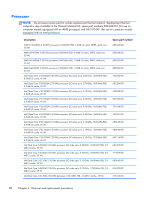
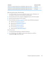
Power connector cable NOTE: The power connector cable spare part kit includes the bracket. Description For use only on computer models equipped with an AMD processor and a 90-W AC adapter For use only on computer models equipped with an Intel processor and a 120-W AC adapter For use only on computer models equipped with an Intel processor and a 90-W AC adapter Spare part number 681973-001 682059-001 682058-001 Before removing the power connector cable, follow these steps: 1. Turn off the computer. If you are unsure whether the computer is off or in Hibernation, turn the computer on, and then shut it down through the operating system. 2. Disconnect the power from the computer by unplugging the power cord from the computer. 3. Disconnect all external devices from the computer. 4. Remove the battery (see Battery on page 51), and then remove the following components: a. Hard drive (see Hard drive on page 52) b. Optical drive (see Optical drive on page 59) c. Keyboard (see Keyboard on page 61) d. Top cover (see Top cover on page 66) e. USB board (see USB board on page 90) f. Subwoofer (see Subwoofer on page 91) Remove the power connector cable: 1. Remove the Phillips PM2.5×5.5 screw (1) that secures the right edge of the system board to the base enclosure. 2. Lift the right edge of the system board (2) until the power connector is accessible. 3. Release the power connector cable (3) from the clips(4) and routing channel built into the base enclosure. Component replacement procedures 93
-
 1
1 -
2
-
3
-
4
-
5
-
6
-
7
-
8
-
9
-
10
-
11
-
12
-
13
-
14
-
15
-
16
-
17
-
18
-
19
-
20
-
21
-
22
-
23
-
24
-
25
-
26
-
27
-
28
-
29
-
30
-
31
-
32
-
33
-
34
-
35
-
36
-
37
-
38
-
39
-
40
-
41
-
42
-
43
-
44
-
45
-
46
-
47
-
48
-
49
-
50
-
51
-
52
-
53
-
54
-
55
-
56
-
57
-
58
-
59
-
60
-
61
-
62
-
63
-
64
-
65
-
66
-
67
-
68
-
69
-
70
-
71
-
72
-
73
-
74
-
75
-
76
-
77
-
78
-
79
-
80
-
81
-
82
-
83
-
84
-
85
-
86
-
87
-
88
-
89
-
90
-
91
-
92
-
93
-
94
-
95
-
 96
96 -
 97
97 -
 98
98 -
 99
99 -
 100
100 -
 101
101 -
 102
102 -
 103
103 -
 104
104 -
 105
105 -
 106
106 -
107
-
108
-
109
-
110
-
111
-
112
-
113
-
114
-
115
-
116
-
117
-
118
-
119
-
120
-
121
-
122
-
123
-
124
-
125
-
126
-
127
-
128
-
129
-
130
 |
 |
