HP HDX18-1020US HP HDX 18 Entertainment PC - Maintenance and Service Guide - Page 50
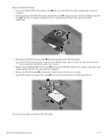
Remove the two Phillips PM2.0×4.0 screws, from the terminals on the WLAN module.
 |
UPC - 884420403616
View all HP HDX18-1020US manuals
Add to My Manuals
Save this manual to your list of manuals |
Page 50 highlights
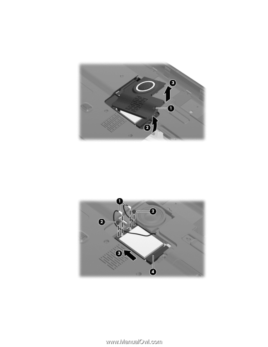
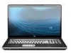
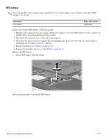
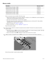
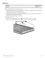
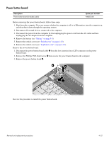
Remove the WLAN module: 1. Loosen the Phillips PM2.5×6.0 captive screw 1 that secures the WLAN module compartment cover to the computer. 2. Lift the right side of the WLAN module compartment cover 2, swing it up and to the left, and then remove the cover 3. The WLAN module compartment cover is included in the Plastics Kit, spare part number 496888-001. 3. Disconnect the WLAN antenna cables 1 from the terminals on the WLAN module. ✎ The black WLAN antenna cable is connected to the WLAN module "Main" terminal. The white WLAN antenna cable is connected to the WLAN module "Aux" terminal. 4. Remove the two Phillips PM2.0×4.0 screws 2 that secure the WLAN module to the computer. (The edge of the module opposite the slot rises away from the computer.) 5. Remove the WLAN module 3 by pulling the module away from the slot at an angle. ✎ WLAN modules are designed with a notch 4 to prevent incorrect insertion into the WLAN module slot. Reverse this procedure to install the WLAN module. Removal and replacement procedures 4-17
-
 1
1 -
2
-
3
-
4
-
5
-
6
-
7
-
8
-
9
-
10
-
11
-
12
-
13
-
14
-
15
-
16
-
17
-
18
-
19
-
20
-
21
-
22
-
23
-
24
-
25
-
26
-
27
-
28
-
29
-
30
-
31
-
32
-
33
-
34
-
35
-
36
-
37
-
38
-
39
-
40
-
41
-
42
-
43
-
44
-
 45
45 -
 46
46 -
 47
47 -
 48
48 -
 49
49 -
 50
50 -
 51
51 -
 52
52 -
 53
53 -
 54
54 -
 55
55 -
56
-
57
-
58
-
59
-
60
-
61
-
62
-
63
-
64
-
65
-
66
-
67
-
68
-
69
-
70
-
71
-
72
-
73
-
74
-
75
-
76
-
77
-
78
-
79
-
80
-
81
-
82
-
83
-
84
-
85
-
86
-
87
-
88
-
89
-
90
-
91
-
92
-
93
-
94
-
95
-
96
-
97
-
98
-
99
-
100
-
101
-
102
-
103
-
104
-
105
-
106
-
107
-
108
-
109
-
110
-
111
-
112
-
113
-
114
-
115
-
116
-
117
-
118
-
119
-
120
-
121
-
122
-
123
-
124
-
125
-
126
-
127
-
128
-
129
-
130
-
131
-
132
-
133
-
134
-
135
-
136
-
137
-
138
 |
 |