HP HDX18-1020US HP HDX 18 Entertainment PC - Maintenance and Service Guide - Page 87
Fan/heat sink assembly, Memory module see
 |
UPC - 884420403616
View all HP HDX18-1020US manuals
Add to My Manuals
Save this manual to your list of manuals |
Page 87 highlights
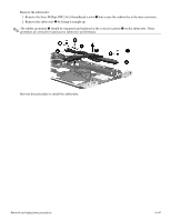
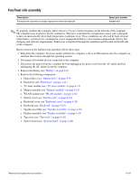
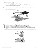
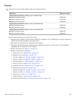
Fan/heat sink assembly Description Fan/heat sink assembly (includes replacement thermal material) Spare part number 496894-001 ✎ To properly ventilate the computer, allow at least a 7.6-cm (3-inch) clearance on the left side of the computer. The computer uses an electric fan for ventilation. The fan is controlled by a temperature sensor and is designed to turn on automatically when high temperature conditions exist. These conditions are affected by high external temperatures, system power consumption, power management/battery conservation configurations, battery fast charging, and software requirements. Exhaust air is displaced through the ventilation grill located on the left side of the computer. Before removing the fan/heat sink assembly, follow these steps: 1. Shut down the computer. If you are unsure whether the computer is off or in Hibernation, turn the computer on, and then shut it down through the operating system. 2. Disconnect all external devices connected to the computer. 3. Disconnect the power from the computer by first unplugging the power cord from the AC outlet and then unplugging the AC adapter from the computer. 4. Remove the battery (see "Battery" on page 4-8). 5. Remove the following components: a. Optical drive (see "Optical drive" on page 4-9) b. Hard drive (see "Hard drive" on page 4-11) c. TV tuner module (see "TV tuner module" on page 4-13) d. Memory module (see "Memory module" on page 4-15) e. WLAN module (see "WLAN module" on page 4-16) f. Switch cover (see "Switch cover" on page 4-18) g. Keyboard cover (see "Keyboard cover" on page 4-20) h. Keyboard (see "Keyboard" on page 4-24) i. Speaker assembly (see "Speaker assembly" on page 4-30) j. Display assembly (see "Display assembly" on page 4-31) k. Top cover (see "Top cover" on page 4-38) l. System board (see "System board" on page 4-44) Removal and replacement procedures 4-54
-
 1
1 -
2
-
3
-
4
-
5
-
6
-
7
-
8
-
9
-
10
-
11
-
12
-
13
-
14
-
15
-
16
-
17
-
18
-
19
-
20
-
21
-
22
-
23
-
24
-
25
-
26
-
27
-
28
-
29
-
30
-
31
-
32
-
33
-
34
-
35
-
36
-
37
-
38
-
39
-
40
-
41
-
42
-
43
-
44
-
45
-
46
-
47
-
48
-
49
-
50
-
51
-
52
-
53
-
54
-
55
-
56
-
57
-
58
-
59
-
60
-
61
-
62
-
63
-
64
-
65
-
66
-
67
-
68
-
69
-
70
-
71
-
72
-
73
-
74
-
75
-
76
-
77
-
78
-
79
-
80
-
81
-
 82
82 -
 83
83 -
 84
84 -
 85
85 -
 86
86 -
 87
87 -
 88
88 -
 89
89 -
 90
90 -
 91
91 -
 92
92 -
93
-
94
-
95
-
96
-
97
-
98
-
99
-
100
-
101
-
102
-
103
-
104
-
105
-
106
-
107
-
108
-
109
-
110
-
111
-
112
-
113
-
114
-
115
-
116
-
117
-
118
-
119
-
120
-
121
-
122
-
123
-
124
-
125
-
126
-
127
-
128
-
129
-
130
-
131
-
132
-
133
-
134
-
135
-
136
-
137
-
138
 |
 |