HP HDX18-1020US HP HDX 18 Entertainment PC - Maintenance and Service Guide - Page 80
Fan
 |
UPC - 884420403616
View all HP HDX18-1020US manuals
Add to My Manuals
Save this manual to your list of manuals |
Page 80 highlights
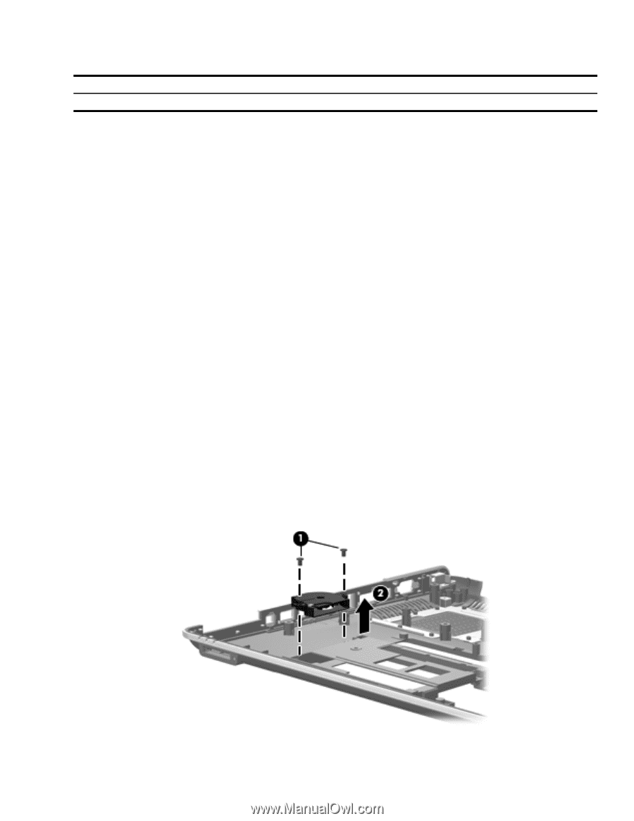
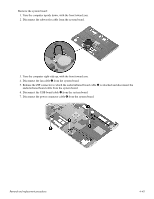
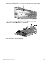
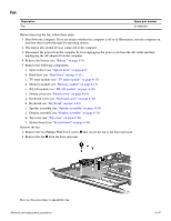
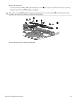
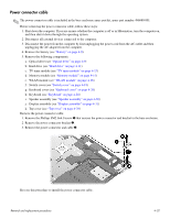
Fan Description Fan Spare part number 514290-001 Before removing the fan, follow these steps: 1. Shut down the computer. If you are unsure whether the computer is off or in Hibernation, turn the computer on, and then shut it down through the operating system. 2. Disconnect all external devices connected to the computer. 3. Disconnect the power from the computer by first unplugging the power cord from the AC outlet and then unplugging the AC adapter from the computer. 4. Remove the battery (see "Battery" on page 4-8). 5. Remove the following components: a. Optical drive (see "Optical drive" on page 4-9) b. Hard drive (see "Hard drive" on page 4-11) c. TV tuner module (see "TV tuner module" on page 4-13) d. Memory module (see "Memory module" on page 4-15) e. WLAN module (see "WLAN module" on page 4-16) f. Switch cover (see "Switch cover" on page 4-18) g. Keyboard cover (see "Keyboard cover" on page 4-20) h. Keyboard (see "Keyboard" on page 4-24) i. Speaker assembly (see "Speaker assembly" on page 4-30) j. Display assembly (see "Display assembly" on page 4-31) k. Top cover (see "Top cover" on page 4-38) l. System board (see "System board" on page 4-44) Remove the fan: 1. Remove the two Phillips PM2.0×4.0 screws 1 that secure the fan to the base enclosure. 2. Remove the fan 2 from the base enclosure. Reverse this procedure to install the fan. Removal and replacement procedures 4-47
-
 1
1 -
2
-
3
-
4
-
5
-
6
-
7
-
8
-
9
-
10
-
11
-
12
-
13
-
14
-
15
-
16
-
17
-
18
-
19
-
20
-
21
-
22
-
23
-
24
-
25
-
26
-
27
-
28
-
29
-
30
-
31
-
32
-
33
-
34
-
35
-
36
-
37
-
38
-
39
-
40
-
41
-
42
-
43
-
44
-
45
-
46
-
47
-
48
-
49
-
50
-
51
-
52
-
53
-
54
-
55
-
56
-
57
-
58
-
59
-
60
-
61
-
62
-
63
-
64
-
65
-
66
-
67
-
68
-
69
-
70
-
71
-
72
-
73
-
74
-
 75
75 -
 76
76 -
 77
77 -
 78
78 -
 79
79 -
 80
80 -
 81
81 -
 82
82 -
 83
83 -
 84
84 -
 85
85 -
86
-
87
-
88
-
89
-
90
-
91
-
92
-
93
-
94
-
95
-
96
-
97
-
98
-
99
-
100
-
101
-
102
-
103
-
104
-
105
-
106
-
107
-
108
-
109
-
110
-
111
-
112
-
113
-
114
-
115
-
116
-
117
-
118
-
119
-
120
-
121
-
122
-
123
-
124
-
125
-
126
-
127
-
128
-
129
-
130
-
131
-
132
-
133
-
134
-
135
-
136
-
137
-
138
 |
 |