HP Mini CQ10-100 Compaq Mini CQ10 Notebook PC and Compaq Mini 102 Notebook PC - Page 55
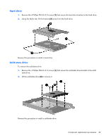
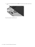
Remove the 8 Phillips PM2.5×6.0 screws, Release the ZIF connector
 |
View all HP Mini CQ10-100 manuals
Add to My Manuals
Save this manual to your list of manuals |
Page 55 highlights
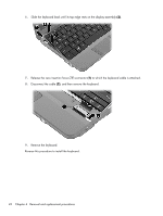
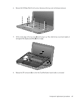
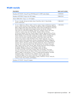
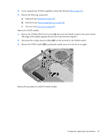
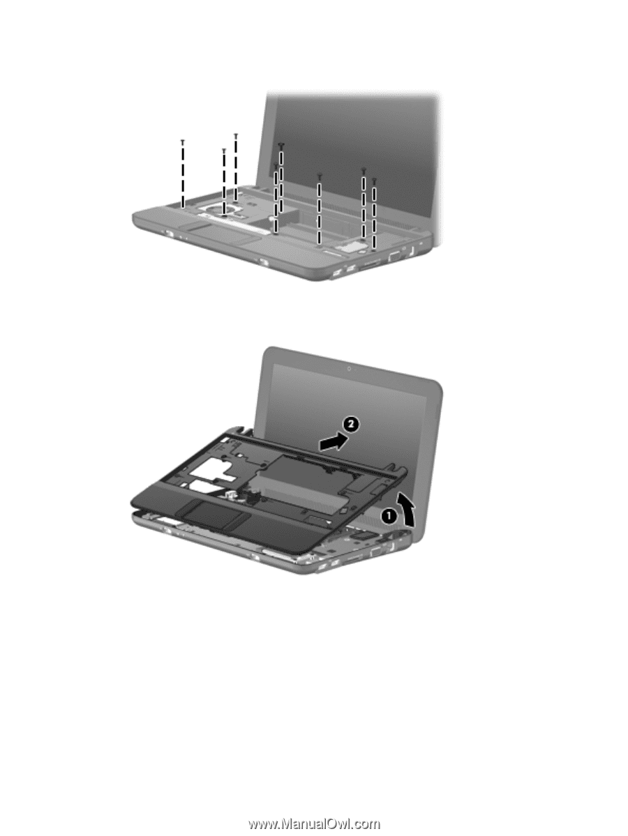
6. Remove the 8 Phillips PM2.5×6.0 screws that secure the top cover to the base enclosure. 7. Lift the inside edge of the top cover (1) and swing it up. Then slide the top cover back slightly to rest against the display assembly (2) at an angle. 8. Release the ZIF connector (1) to which the TouchPad button board cable is connected. Component replacement procedures 47
-
 1
1 -
2
-
3
-
4
-
5
-
6
-
7
-
8
-
9
-
10
-
11
-
12
-
13
-
14
-
15
-
16
-
17
-
18
-
19
-
20
-
21
-
22
-
23
-
24
-
25
-
26
-
27
-
28
-
29
-
30
-
31
-
32
-
33
-
34
-
35
-
36
-
37
-
38
-
39
-
40
-
41
-
42
-
43
-
44
-
45
-
46
-
47
-
48
-
49
-
 50
50 -
 51
51 -
 52
52 -
 53
53 -
 54
54 -
 55
55 -
 56
56 -
 57
57 -
 58
58 -
 59
59 -
 60
60 -
61
-
62
-
63
-
64
-
65
-
66
-
67
-
68
-
69
-
70
-
71
-
72
-
73
-
74
-
75
-
76
-
77
-
78
-
79
-
80
-
81
-
82
-
83
-
84
-
85
-
86
-
87
-
88
-
89
-
90
-
91
-
92
-
93
-
94
-
95
-
96
-
97
-
98
-
99
-
100
-
101
-
102
-
103
-
104
-
105
-
106
-
107
-
108
-
109
-
110
-
111
-
112
-
113
-
114
-
115
-
116
-
117
-
118
-
119
 |
 |
6.
Remove the 8 Phillips PM2.5×6.0 screws
that secure the top cover to the base enclosure.
7.
Lift the inside edge of the top cover
(1)
and swing it up. Then slide the top cover back slightly to
rest against the display assembly
(2)
at an angle.
8.
Release the ZIF connector
(1)
to which the TouchPad button board cable is connected.
Component replacement procedures
47