HP ProBook 4520s HP ProBook 4520s Notebook PC and HP ProBook 4720s Notebook PC - Page 65
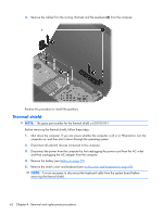
Remove the Phillips PM2.5×5.0 screw, from the computer.
 |
View all HP ProBook 4520s manuals
Add to My Manuals
Save this manual to your list of manuals |
Page 65 highlights
4. Remove the battery (see Battery on page 50). 5. Remove the switch cover and keyboard (see Switch cover and keyboard on page 51). NOTE: It is not necessary to disconnect the keyboard cable from the system board to remove the optical drive. Remove the optical drive: 1. Position the computer with the right side toward you. 2. Remove the Phillips PM2.5×5.0 screw (1) that secures the optical drive to the computer. 3. Insert a flat-bladed screwdriver or similar tool into the optical drive tab access (2) and press the tab to the right to release the optical drive from the computer. 4. Remove the optical drive (3) from the computer. NOTE: 15.6-in model shown below 5. If it is necessary to replace the optical drive bracket, position the optical drive with the rear toward you. 6. Remove the two Phillips PM2.0×2.0 screws (1) that secure the optical drive bracket to the optical drive. Component replacement procedures 57
-
 1
1 -
2
-
3
-
4
-
5
-
6
-
7
-
8
-
9
-
10
-
11
-
12
-
13
-
14
-
15
-
16
-
17
-
18
-
19
-
20
-
21
-
22
-
23
-
24
-
25
-
26
-
27
-
28
-
29
-
30
-
31
-
32
-
33
-
34
-
35
-
36
-
37
-
38
-
39
-
40
-
41
-
42
-
43
-
44
-
45
-
46
-
47
-
48
-
49
-
50
-
51
-
52
-
53
-
54
-
55
-
56
-
57
-
58
-
59
-
 60
60 -
 61
61 -
 62
62 -
 63
63 -
 64
64 -
 65
65 -
 66
66 -
 67
67 -
 68
68 -
 69
69 -
 70
70 -
71
-
72
-
73
-
74
-
75
-
76
-
77
-
78
-
79
-
80
-
81
-
82
-
83
-
84
-
85
-
86
-
87
-
88
-
89
-
90
-
91
-
92
-
93
-
94
-
95
-
96
-
97
-
98
-
99
-
100
-
101
-
102
-
103
-
104
-
105
-
106
-
107
-
108
-
109
-
110
-
111
-
112
-
113
-
114
-
115
-
116
-
117
-
118
-
119
-
120
-
121
-
122
-
123
-
124
-
125
-
126
-
127
-
128
-
129
-
130
-
131
-
132
-
133
-
134
-
135
-
136
-
137
-
138
-
139
-
140
-
141
-
142
-
143
-
144
-
145
-
146
-
147
-
148
-
149
-
150
-
151
-
152
-
153
-
154
-
155
-
156
-
157
-
158
-
159
-
160
-
161
-
162
-
163
-
164
 |
 |
