HP ProBook 4520s HP ProBook 4520s Notebook PC and HP ProBook 4720s Notebook PC - Page 77
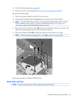
Heat sink and fan, by pulling the module away from the slot at an angle.
 |
View all HP ProBook 4520s manuals
Add to My Manuals
Save this manual to your list of manuals |
Page 77 highlights
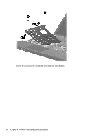
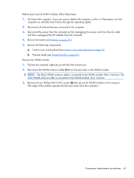
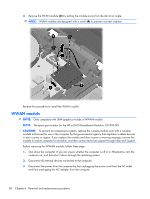
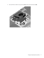
4. Remove the battery (see Battery on page 50). 5. Remove the switch cover and keyboard (see Switch cover and keyboard on page 51) Remove the WWAN module: 1. Position the computer right-side up with the front toward you. 2. Disconnect the WWAN antenna cables (1) from the terminals on the WWAN module. NOTE: The red WWAN antenna cable is connected to the WWAN module "Main" terminal. The blue WWAN antenna cable is connected to the WWAN module "Aux" terminal. The terminals and cables are both identified by number and color. 3. Remove the two Torx M2.5×6.0 screws (2) that secure the WWAN module to the computer. (The edge of the module opposite the slot rises away from the computer.) 4. Remove the WWAN module (3) by pulling the module away from the slot at an angle. NOTE: WWAN modules are designed with a notch (4) to prevent incorrect insertion. Reverse this procedure to install the WWAN module. Heat sink and fan NOTE: The heat sink spare part kit includes replacement thermal material. Component replacement procedures 69
-
 1
1 -
2
-
3
-
4
-
5
-
6
-
7
-
8
-
9
-
10
-
11
-
12
-
13
-
14
-
15
-
16
-
17
-
18
-
19
-
20
-
21
-
22
-
23
-
24
-
25
-
26
-
27
-
28
-
29
-
30
-
31
-
32
-
33
-
34
-
35
-
36
-
37
-
38
-
39
-
40
-
41
-
42
-
43
-
44
-
45
-
46
-
47
-
48
-
49
-
50
-
51
-
52
-
53
-
54
-
55
-
56
-
57
-
58
-
59
-
60
-
61
-
62
-
63
-
64
-
65
-
66
-
67
-
68
-
69
-
70
-
71
-
 72
72 -
 73
73 -
 74
74 -
 75
75 -
 76
76 -
 77
77 -
 78
78 -
 79
79 -
 80
80 -
 81
81 -
 82
82 -
83
-
84
-
85
-
86
-
87
-
88
-
89
-
90
-
91
-
92
-
93
-
94
-
95
-
96
-
97
-
98
-
99
-
100
-
101
-
102
-
103
-
104
-
105
-
106
-
107
-
108
-
109
-
110
-
111
-
112
-
113
-
114
-
115
-
116
-
117
-
118
-
119
-
120
-
121
-
122
-
123
-
124
-
125
-
126
-
127
-
128
-
129
-
130
-
131
-
132
-
133
-
134
-
135
-
136
-
137
-
138
-
139
-
140
-
141
-
142
-
143
-
144
-
145
-
146
-
147
-
148
-
149
-
150
-
151
-
152
-
153
-
154
-
155
-
156
-
157
-
158
-
159
-
160
-
161
-
162
-
163
-
164
 |
 |
