HP ProLiant DL380p HP ProLiant DL380p Gen8 Server User Guide - Page 57
Installing the flash-backed write cache capacitor pack, Power down the server
 |
View all HP ProLiant DL380p manuals
Add to My Manuals
Save this manual to your list of manuals |
Page 57 highlights
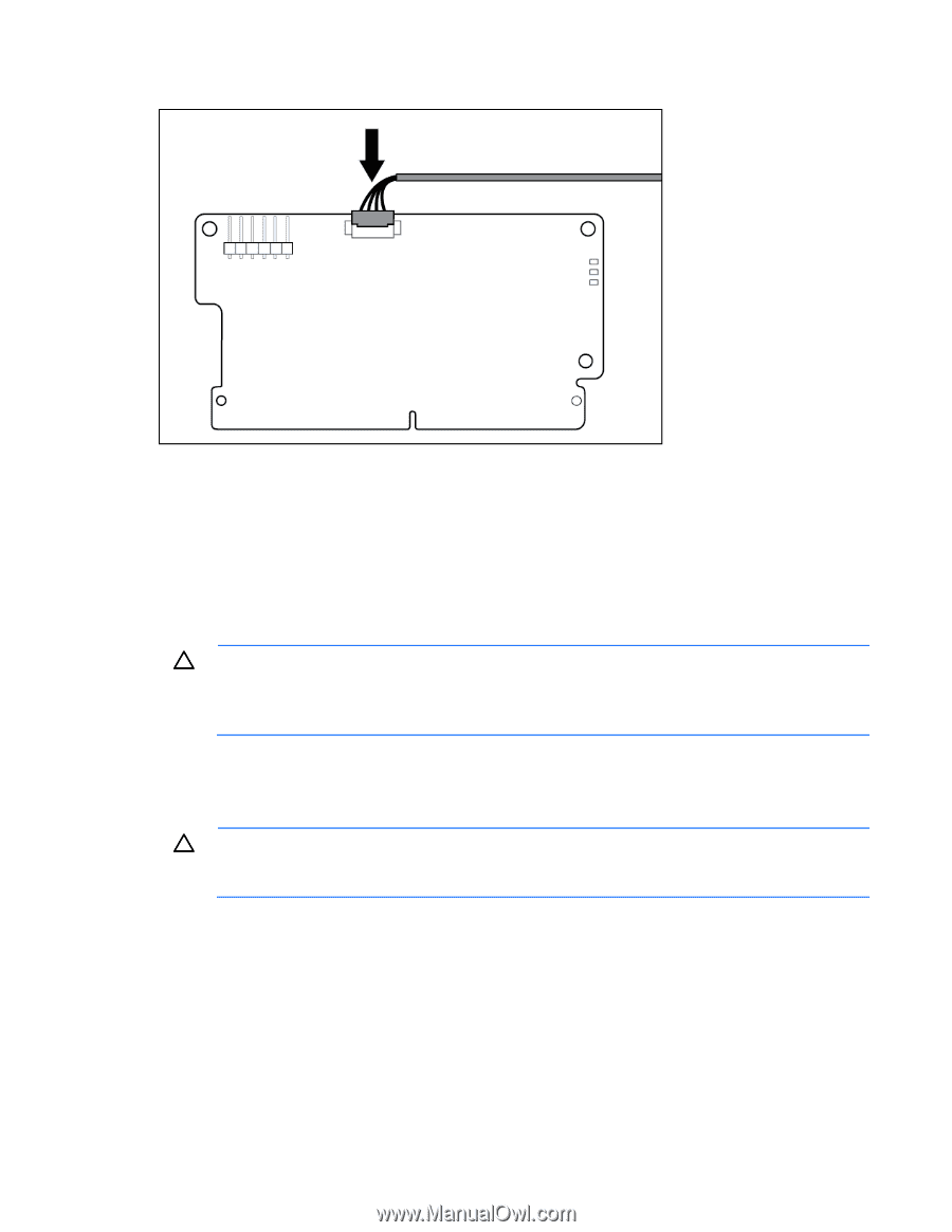
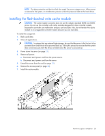
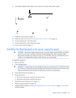
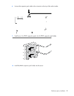
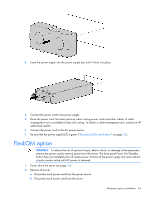
8. Connect the capacitor pack cable to the connector on the top of the cache module. 9. Install the access panel (on page 23). 10. Install the server into the rack ("Installing the server into the rack" on page 36). 11. Connect each power cord to the server. 12. Connect each power cord to the power source. 13. Power up the server (on page 21). Installing the flash-backed write cache capacitor pack CAUTION: The cache module connector does not use the industry standard DDR3 mini DIMM pinout. Do not use this controller with cache modules designed for other controller models, because the controller can malfunction and you can lose data. Also, do not transfer this cache module to an unsupported controller model, because you can lose data. To install the component: 1. Back up all data. 2. Close all applications. CAUTION: In systems that use external data storage, be sure that the server is the first unit to be powered down and the last to be powered back up. Taking this precaution ensures that the system does not erroneously mark the drives as failed when the server is powered up. 3. Power down the server (on page 21). 4. Remove all power: a. Disconnect each power cord from the power source. b. Disconnect each power cord from the server. 5. Extend the server from the rack (on page 21). 6. Remove the access panel (on page 22). 7. Install the FBWC module ("Installing the flash-backed write cache module" on page 56), if it is not already installed. Hardware options installation 57
-
 1
1 -
2
-
3
-
4
-
5
-
6
-
7
-
8
-
9
-
10
-
11
-
12
-
13
-
14
-
15
-
16
-
17
-
18
-
19
-
20
-
21
-
22
-
23
-
24
-
25
-
26
-
27
-
28
-
29
-
30
-
31
-
32
-
33
-
34
-
35
-
36
-
37
-
38
-
39
-
40
-
41
-
42
-
43
-
44
-
45
-
46
-
47
-
48
-
49
-
50
-
51
-
 52
52 -
 53
53 -
 54
54 -
 55
55 -
 56
56 -
 57
57 -
 58
58 -
 59
59 -
 60
60 -
 61
61 -
 62
62 -
63
-
64
-
65
-
66
-
67
-
68
-
69
-
70
-
71
-
72
-
73
-
74
-
75
-
76
-
77
-
78
-
79
-
80
-
81
-
82
-
83
-
84
-
85
-
86
-
87
-
88
-
89
-
90
-
91
-
92
-
93
-
94
-
95
-
96
-
97
-
98
-
99
-
100
-
101
-
102
-
103
-
104
-
105
-
106
-
107
-
108
-
109
-
110
-
111
-
112
-
113
-
114
-
115
-
116
-
117
-
118
-
119
-
120
-
121
-
122
-
123
-
124
-
125
-
126
-
127
-
128
 |
 |