HP Rp3000 Hardware Reference Guide - HP rp3000
HP Rp3000 - Point of Sale System Manual
 |
UPC - 884420494096
View all HP Rp3000 manuals
Add to My Manuals
Save this manual to your list of manuals |
HP Rp3000 manual content summary:
- HP Rp3000 | Hardware Reference Guide - HP rp3000 - Page 1
Hardware Reference Guide HP rp3000 - HP Rp3000 | Hardware Reference Guide - HP rp3000 - Page 2
information that is protected by copyright. No part of this document may be photocopied, reproduced, or translated to another language without the prior written consent of Hewlett-Packard Company. Hardware Reference Guide HP rp3000 First Edition (August 2008) Document Part Number: 498354-001 - HP Rp3000 | Hardware Reference Guide - HP rp3000 - Page 3
About This Book This guide provides basic information for upgrading this computer model. WARNING! Text set off in this manner indicates that failure to follow directions could result in bodily harm or loss of life. CAUTION: Text - HP Rp3000 | Hardware Reference Guide - HP rp3000 - Page 4
iv About This Book ENWW - HP Rp3000 | Hardware Reference Guide - HP rp3000 - Page 5
models 17 Removing and Replacing the 3.5-inch Internal SATA Hard Drive 21 Appendix A Specifications Appendix B PoweredUSB Ports (some models) Appendix C Powered Serial Ports Removing the Powered Serial Port Caps 32 Configuring Power to a Serial Port ...33 Appendix D Battery Replacement ENWW v - HP Rp3000 | Hardware Reference Guide - HP rp3000 - Page 6
...43 Cable Lock ...43 Padlock ...44 HP Business PC Security Lock 44 Appendix F Electrostatic Discharge Preventing Electrostatic Damage ...47 Grounding Methods ...47 Appendix G Computer Operating Guidelines, Routine Care and Shipping Preparation Computer Operating Guidelines and Routine Care 48 - HP Rp3000 | Hardware Reference Guide - HP rp3000 - Page 7
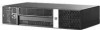
on some computer models only). Instructions for using the utility are provided in the Troubleshooting Guide on the Documentation and Diagnostics DVD. Figure 1-1 HP Point of Sale System rp3000 Configuration NOTE: This product features two optional PoweredUSB ports. In the point of sale industry - HP Rp3000 | Hardware Reference Guide - HP rp3000 - Page 8
drive is a DVD-ROM or DVD+R/RW drive. The Power On Light is normally green when the power is on. If it is flashing red, there is a problem with the computer and it is displaying a diagnostic code. Refer to the Troubleshooting Guide on the Documentation and Diagnostics DVD to interpret the code - HP Rp3000 | Hardware Reference Guide - HP rp3000 - Page 9
Cord Connector NOTE: Arrangement and number of connectors may vary by model. * Serial ports can be configured to support powered serial port. Refer to Powered Serial Ports on page 31 for details. NOTE: An optional ReadyBoost module is available from HP, but it can only be installed if the optional - HP Rp3000 | Hardware Reference Guide - HP rp3000 - Page 10
1-2 Locking the Drive Door Serial Number Location Each computer has a unique serial number and product ID number located on the back of the computer. Keep these numbers available for use when contacting customer service for assistance. Figure 1-3 Serial Number and Product ID Location 4 Chapter - HP Rp3000 | Hardware Reference Guide - HP rp3000 - Page 11
. It describes proper workstation, setup, posture, and health and work habits for computer users, and provides important electrical and mechanical safety information. This guide is located on the Web at http://www.hp.com/ergo and on the Documentation and Diagnostics DVD. CAUTION: Static electricity - HP Rp3000 | Hardware Reference Guide - HP rp3000 - Page 12
any security devices that prohibit opening the computer. 2. Remove all removable media, such as compact discs, from the computer. 3. Turn off the computer properly through the operating system, then turn off any external devices. 4. Disconnect the power cord from the power outlet and disconnect any - HP Rp3000 | Hardware Reference Guide - HP rp3000 - Page 13
On some models, a bezel blank covering the 5.25-inch external drive bay must be removed before installing a drive. To remove a bezel blank: 1. Remove the computer cover and place it upside down on a stable surface. 2. Push outward on the two retaining tabs that hold the bezel blank in place (1) then - HP Rp3000 | Hardware Reference Guide - HP rp3000 - Page 14
JEDEC SPD information In addition, the computer supports: ● 256Mbit, 512Mbit, and 1Gbit non-ECC memory technologies ● single-sided and double-sided DIMMs ● DIMMs constructed with x8 and x16 DDR devices; DIMMs constructed with x4 SDRAM are not supported NOTE: The system will accept PC2-6400 800 MHz - HP Rp3000 | Hardware Reference Guide - HP rp3000 - Page 15
modules. Regardless of the power-on state, voltage is always supplied to the memory modules as long as the computer is plugged into an active AC outlet. Adding or removing memory modules while voltage is present may cause irreparable damage to the memory modules or system board. If you see an LED - HP Rp3000 | Hardware Reference Guide - HP rp3000 - Page 16
modules. Regardless of the power-on state, voltage is always supplied to the memory modules as long as the computer is plugged into an active AC outlet. Adding or removing memory modules while voltage is present may cause irreparable damage to the memory modules or system board. If you see an LED - HP Rp3000 | Hardware Reference Guide - HP rp3000 - Page 17
. Figure 2-7 Lowering the Drive Cage 12. Replace the computer cover. 13. Reconnect the power cord and any external devices, then turn on the computer. The computer should automatically recognize the additional memory when you turn on the computer. 14. Lock any security devices that were disengaged - HP Rp3000 | Hardware Reference Guide - HP rp3000 - Page 18
any security devices that prohibit opening the computer. 2. Remove all removable media, such as compact discs, from the computer. 3. Turn off the computer properly through the operating system, then turn off any external devices. 4. Disconnect the power cord from the power outlet and disconnect any - HP Rp3000 | Hardware Reference Guide - HP rp3000 - Page 19
6. Remove the screw that secures the expansion card slot cover or the existing expansion card to the chassis. Figure 2-9 Removing the Slot Cover Screw 7. Remove the expansion slot cover or the existing expansion card. a. If you are installing an expansion card in a vacant socket, slide the expansion - HP Rp3000 | Hardware Reference Guide - HP rp3000 - Page 20
Store the removed card in anti-static packaging. 9. If you are not installing a new expansion card, install an expansion slot cover to close the open slot. CAUTION: After removing an expansion card, you must replace it with a new card or expansion slot cover for proper cooling of internal components - HP Rp3000 | Hardware Reference Guide - HP rp3000 - Page 21
any security devices that were disengaged when the computer cover was removed. 16. Reconfigure the computer, if necessary. Refer to the Computer Setup (F10) Utility Guide on the Documentation and Diagnostics DVD for instructions about using Computer Setup. ENWW Removing or Installing an Expansion - HP Rp3000 | Hardware Reference Guide - HP rp3000 - Page 22
with optical drive installed (some models) To verify the type, size, and capacity of the storage devices installed in the computer, run Computer Setup. Refer to the Computer Setup (F10) Utility Guide on the Documentation and Diagnostics DVD for more information. 16 Chapter 2 Hardware Upgrades ENWW - HP Rp3000 | Hardware Reference Guide - HP rp3000 - Page 23
or drive: If you are inserting or removing a drive, shut down the operating system properly, turn off the computer, and unplug the power cord. Do not remove a drive while the computer is on or in standby mode. Before handling a drive, ensure that you are discharged of static electricity. While - HP Rp3000 | Hardware Reference Guide - HP rp3000 - Page 24
any security devices that prohibit opening the computer. 2. Remove all removable media, such as compact discs, from the computer. 3. Turn off the computer properly through the operating system, then turn off any external devices. 4. Disconnect the power cord from the power outlet and disconnect any - HP Rp3000 | Hardware Reference Guide - HP rp3000 - Page 25
8. Remove the four screws that secure the drive to the drive cage (1), and then slide the drive forward out of the drive bay (2). Figure 2-18 Removing the Optical Drive NOTE: When replacing a drive, use the four retainer screws that were used for the old drive when installing the new drive. To - HP Rp3000 | Hardware Reference Guide - HP rp3000 - Page 26
2-21 Lowering the Drive Cage 7. Replace the computer cover. 8. Reconnect the power cord and any external devices, then turn on the computer. 9. Lock any security devices that were disengaged when the computer cover was removed. The system automatically recognizes the drive and reconfigures the - HP Rp3000 | Hardware Reference Guide - HP rp3000 - Page 27
any security devices that prohibit opening the computer. 2. Remove all removable media, such as compact discs, from the computer. 3. Turn off the computer properly through the operating system, then turn off any external devices. 4. Disconnect the power cord from the power outlet and disconnect any - HP Rp3000 | Hardware Reference Guide - HP rp3000 - Page 28
7. Disconnect the data cable (1) and power cable (2) from the back of the primary hard drive. Figure 2-23 Disconnecting the Hard Drive Data and Power Cables 8. Remove the four screws on top of the drive cage that secure the hard drive in the bay. Figure 2-24 Removing the Hard Drive - HP Rp3000 | Hardware Reference Guide - HP rp3000 - Page 29
the hard drive bay in the drive cage so that the bottom of the hard drive is next to the optical drive compartment and the power and data connectors are up. Slide the drive all the way down into the drive cage until it stops. Figure 2-26 Installing the Hard Drive - HP Rp3000 | Hardware Reference Guide - HP rp3000 - Page 30
drive. NOTE: The data cable must be connected to the dark blue connector labeled SATA 0 on the system board to avoid any hard drive performance problems. Figure 2-28 Connecting the Hard Drive Data and Power Cables CAUTION: Never crease or bend a SATA data cable tighter than a 30 mm (1.18 in) radius - HP Rp3000 | Hardware Reference Guide - HP rp3000 - Page 31
computer cover. 7. Reconnect the power cord and any external devices, then turn on the computer. 8. Lock any security devices that were disengaged when the computer cover was removed. NOTE: If you replaced the hard drive, use the Recovery Disc Set to restore the operating system, software drivers - HP Rp3000 | Hardware Reference Guide - HP rp3000 - Page 32
100-240 VAC Rated Line Frequency 50-60 Hz 50-60 Hz Power Output 150 W 150 W Rated Input Current (maximum)1 3A @ 90 VAC 1.5A @ 180 VAC 1 This system utilizes an active power factor corrected power supply. This allows the system to pass the CE mark requirements for use in the countries of - HP Rp3000 | Hardware Reference Guide - HP rp3000 - Page 33
The rp3000 supports either a ReadyBoost module or a PoweredUSB expansion card, but it will not support both of these options. Figure B-1 PoweredUSB Ports The 24 1. Remove/disengage any security devices that prohibit opening the computer. 2. Remove all removable media, such as compact discs, from - HP Rp3000 | Hardware Reference Guide - HP rp3000 - Page 34
the system board as long as the system is plugged into an active AC outlet. You must disconnect the power cord to avoid damage to the internal components of the computer. 5. Remove the computer cover. B-4 Removing the PoweredUSB Expansion Card 28 Appendix B PoweredUSB Ports (some models) ENWW - HP Rp3000 | Hardware Reference Guide - HP rp3000 - Page 35
opening for the ports on the rear of the chassis, you must remove the panel. You may need to remove the power Powered USB expansion card. Figure B-5 Installing the PoweredUSB Expansion Card 9. Return the drive cage to the down position. Figure B-6 Lowering the Drive Cage 10. Replace the computer - HP Rp3000 | Hardware Reference Guide - HP rp3000 - Page 36
11. Reconnect the power cord and any external devices, then turn on the computer. 12. Lock any security devices that were disengaged when the computer cover was removed. 30 Appendix B PoweredUSB Ports (some models) ENWW - HP Rp3000 | Hardware Reference Guide - HP rp3000 - Page 37
standard on the computer. Some models have a powered serial port expansion card installed that supplies two additional powered serial ports, COM 3 and COM 4. Figure C-1 Powered Serial Ports Item Description 1 COM 1 2 COM 2 3 COM 3 (some models) 4 COM 4 (some models) Supports +5V Yes Yes - HP Rp3000 | Hardware Reference Guide - HP rp3000 - Page 38
the Powered Serial Port Caps If the powered serial ports have been configured for power from the factory, they will be covered by protective plastic caps. Turn off the computer and remove the caps before connecting powered serial Point of Sale devices. Figure C-2 Removing the Powered Serial Port - HP Rp3000 | Hardware Reference Guide - HP rp3000 - Page 39
Power to a Serial Port The serial ports on the HP Point of Sale System computer can be configured as standard (non-powered) serial ports or powered serial ports. Some Point of Sale devices use a powered serial port. If the serial port is configured as a powered port, devices that support a powered - HP Rp3000 | Hardware Reference Guide - HP rp3000 - Page 40
Name COM 3 COM 4 To configure power to the serial ports: 1. Remove/disengage any security devices that prohibit opening the computer. 2. Remove all removable media, such as compact discs, from the computer. 3. Turn off the computer properly through the operating system, then turn off any external - HP Rp3000 | Hardware Reference Guide - HP rp3000 - Page 41
are changing the system board COM 1 or COM 2 serial port configuration: a. Raise the drive cage to the upright position. Figure C-5 Rotating the Drive Cage Up b. Place jumpers and jumper wires on the appropriate pins for COM 1 (1) and COM 2 (2). (See Table C-1 Configuring Serial Port Power on page - HP Rp3000 | Hardware Reference Guide - HP rp3000 - Page 42
cage to the down position. Figure C-7 Lowering the Drive Cage 7. If you are changing the Powered Serial Port Expansion Card COM 3 or COM 4 serial port configuration: a. Locate the Powered Serial Port Expansion Card in the expansion card slot. b. Remove the screw that secures the expansion card to - HP Rp3000 | Hardware Reference Guide - HP rp3000 - Page 43
pins for COM 3 (1) and COM 4 (2). (See Table C-1 Configuring Serial Port Power on page 39 to determine the appropriate pins.) Figure C-9 COM 3 and COM 4 Jumpers d. To install the Powered Serial Port Expansion Card, align the bracket on the card with the open slot on the rear of the chassis and press - HP Rp3000 | Hardware Reference Guide - HP rp3000 - Page 44
the power cord and any external devices, then turn on the computer. 10. Lock any security devices that were disengaged when the computer cover was removed. 11. If the serial ports are configured in powered mode, connect the powered Point of Sale device. 38 Appendix C Powered Serial Ports ENWW - HP Rp3000 | Hardware Reference Guide - HP rp3000 - Page 45
Table C-1 Configuring Serial Port Power NOTE: The first row at the top of the table above illustrates the default setting. DSUB pins 1 and 9 can be configured independently of one another. ENWW Configuring Power to a Serial Port 39 - HP Rp3000 | Hardware Reference Guide - HP rp3000 - Page 46
www.hp.com/ recycle. 1. Remove/disengage any security devices that prohibit opening the computer. 2. Remove all removable media, such as compact discs, from the computer. 3. Turn off the computer properly through the operating system, then turn off any external devices. 4. Disconnect the power cord - HP Rp3000 | Hardware Reference Guide - HP rp3000 - Page 47
6. Raise the drive cage to the upright position. Figure D-1 Rotating the Drive Cage Up 7. Locate the battery and battery holder on the system board. 8. To release the battery from its holder, squeeze the metal clamp that extends above one edge of the battery. When the battery pops up, - HP Rp3000 | Hardware Reference Guide - HP rp3000 - Page 48
the Drive Cage 11. Replace the computer cover. 12. Plug in the computer and turn on power to the computer. 13. Reset the date and time, your passwords, and any special system setups using Computer Setup. Refer to the Computer Setup (F10) Utility Guide on the Documentation and Diagnostics DVD - HP Rp3000 | Hardware Reference Guide - HP rp3000 - Page 49
E External Security Devices NOTE: For information on data security features, refer to the Computer Setup (F10) Utility Guide and the Desktop Management Guide on the Documentation and Diagnostics DVD. Installing a Security Lock The security locks displayed below and on the following page can be used - HP Rp3000 | Hardware Reference Guide - HP rp3000 - Page 50
Padlock Figure E-2 Installing a Padlock HP Business PC Security Lock 1. Fasten the security cable by looping it around a stationary object. Figure E-3 Securing the Cable to a Fixed Object 44 Appendix E External Security Devices ENWW - HP Rp3000 | Hardware Reference Guide - HP rp3000 - Page 51
2. Thread any peripheral device cables that you want to secure through the lock. Figure E-4 Threading the Peripheral Device Cables 3. Screw the lock to the chassis using the screw provided. Figure E-5 Attaching the Lock to the Chassis ENWW Installing a Security Lock 45 - HP Rp3000 | Hardware Reference Guide - HP rp3000 - Page 52
4. Insert the plug end of the security cable into the lock (1) and push the button in (2) to engage the lock. Use the key provided to disengage the lock. Figure E-6 Engaging the Lock 46 Appendix E External Security Devices ENWW - HP Rp3000 | Hardware Reference Guide - HP rp3000 - Page 53
service kit with a folding static-dissipating work mat. If you do not have any of the suggested equipment for proper grounding, contact an HP authorized dealer, reseller, or service provider. NOTE: For more information on static electricity, contact an HP authorized dealer, reseller, or service - HP Rp3000 | Hardware Reference Guide - HP rp3000 - Page 54
guidelines listed above will still apply. ● Keep liquids away from the computer and keyboard. ● Never cover the ventilation slots on the monitor with any type of material. ● Install or enable power management functions of the operating system or other software, including sleep states. ● Turn - HP Rp3000 | Hardware Reference Guide - HP rp3000 - Page 55
and external devices from their power sources, then from the computer. NOTE: Ensure that all boards are seated properly and secured in the board slots before shipping the computer. 6. Pack the system components and external devices in their original packing boxes or similar packaging with sufficient - HP Rp3000 | Hardware Reference Guide - HP rp3000 - Page 56
43 HP Business PC Security Lock 44 padlock 44 sliding drive door 4 M memory supply 26 powered serial ports configuring 33 expansion card jumpers 33 locations 31 removing caps 32 system board jumpers 33 product ID location 4 R rear panel components 3 removing battery 40 bezel blanks 7 computer - HP Rp3000 | Hardware Reference Guide - HP rp3000 - Page 57
Business PC Security Lock 44 padlock 44 serial connectors 3, 31 serial number location 4 shipping preparation 49 specifications computer 26 memory 8 U unlocking computer cover 43 USB ports Powered 27 rear panel 3 V ventilation guidelines 48 W Web site HP recycling programs 40 Safety & Comfort Guide
-
 1
1 -
 2
2 -
 3
3 -
 4
4 -
 5
5 -
 6
6 -
 7
7 -
8
-
9
-
10
-
11
-
12
-
13
-
14
-
15
-
16
-
17
-
18
-
19
-
20
-
21
-
22
-
23
-
24
-
25
-
26
-
27
-
28
-
29
-
30
-
31
-
32
-
33
-
34
-
35
-
36
-
37
-
38
-
39
-
40
-
41
-
42
-
43
-
44
-
45
-
46
-
47
-
48
-
49
-
50
-
51
-
52
-
53
-
54
-
55
-
56
-
57
 |
 |

Hardware Reference Guide
HP rp3000