HP Rp3000 Hardware Reference Guide - HP rp3000 - Page 43
C-9, Installing the Powered Serial Port Expansion Card
 |
UPC - 884420494096
View all HP Rp3000 manuals
Add to My Manuals
Save this manual to your list of manuals |
Page 43 highlights
c. Place jumpers and jumper wires on the appropriate pins for COM 3 (1) and COM 4 (2). (See Table C-1 Configuring Serial Port Power on page 39 to determine the appropriate pins.) Figure C-9 COM 3 and COM 4 Jumpers d. To install the Powered Serial Port Expansion Card, align the bracket on the card with the open slot on the rear of the chassis and press the card straight into the expansion socket (1). Replace the screw that secures the card to the chassis (2). NOTE: When installing an expansion card, press firmly on the card so that the whole connector seats properly in the expansion card slot. Figure C-10 Installing the Powered Serial Port Expansion Card ENWW Configuring Power to a Serial Port 37
-
 1
1 -
2
-
3
-
4
-
5
-
6
-
7
-
8
-
9
-
10
-
11
-
12
-
13
-
14
-
15
-
16
-
17
-
18
-
19
-
20
-
21
-
22
-
23
-
24
-
25
-
26
-
27
-
28
-
29
-
30
-
31
-
32
-
33
-
34
-
35
-
36
-
37
-
 38
38 -
 39
39 -
 40
40 -
 41
41 -
 42
42 -
 43
43 -
 44
44 -
 45
45 -
 46
46 -
 47
47 -
 48
48 -
49
-
50
-
51
-
52
-
53
-
54
-
55
-
56
-
57
 |
 |

c.
Place jumpers and jumper wires on the appropriate pins for COM 3 (1) and COM 4 (2). (See
Table
C
-
1
Configuring Serial Port Power
on page
39
to determine the appropriate pins.)
Figure C-9
COM 3 and COM 4 Jumpers
d.
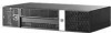
To install the Powered Serial Port Expansion Card, align the bracket on the card with the open
slot on the rear of the chassis and press the card straight into the expansion socket (1).
Replace the screw that secures the card to the chassis (2).
NOTE:
When installing an expansion card, press firmly on the card so that the whole
connector seats properly in the expansion card slot.
Figure C-10
Installing the Powered Serial Port Expansion Card
ENWW
Configuring Power to a Serial Port
37