HP Rp3000 Hardware Reference Guide - HP rp3000 - Page 41
C-5, Configuring Power to a Serial Port
 |
UPC - 884420494096
View all HP Rp3000 manuals
Add to My Manuals
Save this manual to your list of manuals |
Page 41 highlights
6. If you are changing the system board COM 1 or COM 2 serial port configuration: a. Raise the drive cage to the upright position. Figure C-5 Rotating the Drive Cage Up b. Place jumpers and jumper wires on the appropriate pins for COM 1 (1) and COM 2 (2). (See Table C-1 Configuring Serial Port Power on page 39 to determine the appropriate pins.) Figure C-6 COM 1 and COM 2 Jumpers ENWW Configuring Power to a Serial Port 35
-
 1
1 -
2
-
3
-
4
-
5
-
6
-
7
-
8
-
9
-
10
-
11
-
12
-
13
-
14
-
15
-
16
-
17
-
18
-
19
-
20
-
21
-
22
-
23
-
24
-
25
-
26
-
27
-
28
-
29
-
30
-
31
-
32
-
33
-
34
-
35
-
 36
36 -
 37
37 -
 38
38 -
 39
39 -
 40
40 -
 41
41 -
 42
42 -
 43
43 -
 44
44 -
 45
45 -
 46
46 -
47
-
48
-
49
-
50
-
51
-
52
-
53
-
54
-
55
-
56
-
57
 |
 |

6.
If you are changing the system board COM 1 or COM 2 serial port configuration:
a.
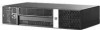
Raise the drive cage to the upright position.
Figure C-5
Rotating the Drive Cage Up
b.
Place jumpers and jumper wires on the appropriate pins for COM 1 (1) and COM 2 (2). (See
Table
C
-
1
Configuring Serial Port Power
on page
39
to determine the appropriate pins.)
Figure C-6
COM 1 and COM 2 Jumpers
ENWW
Configuring Power to a Serial Port
35