Hitachi 60V715 Owners Guide - Page 10
Rear Panel Jacks - settings
 |
View all Hitachi 60V715 manuals
Add to My Manuals
Save this manual to your list of manuals |
Page 10 highlights
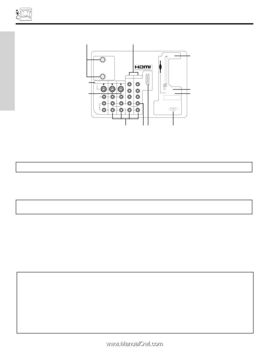
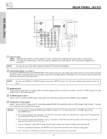
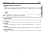
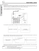
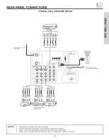
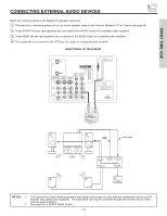
REAR PANEL JACKS FIRST TIME USE ቢ ቦ ANT A CableCARD (Top of card faces right) ቭ ቤ ብ ANT B MONITOR OUT S-VIDEO INPUT 4 INPUT 3 INPUT 2 Y/ VIDEO PB INPUT 1 Y/ VIDEO PB HDMI 1 VIDEO L AUDIO R AUDIO TO HI-FI PR PR (MONO) (MONO) (MONO) (MONO) TV AS CENTER ባ ቫቧ OPTICAL OUT Digital Audio Upgrade Card Apparatus Claims of U.S. Patent Nos. 4,631,603; 4,577,216; 4,819,098; 4,907,093; and 6,381,747 licensed for limited viewing uses only. RS232C 1 2 345 6 789 ቨ ቩ ቪ ቢ Antenna Input ANT A- A 75-Ohm RF antenna or CATV (Cable TV) input. ANT A can be displayed as a main picture or sub-picture. ANT B- A 75-Ohm RF antenna input. ANT B can only be displayed as a main picture. ANT B cannot be displayed as a sub-picture. NOTE: You may ask your local cable company whether DTV services are available. ባ Audio/Video Inputs 1, 2, 3 and 4 By using the INPUTS button and CURSOR PAD of the remote control you can select each video source. Use the audio and video inputs to connect external devices, such as VCRs, camcorders, laserdisc players, DVD players etc. (If you have mono sound, insert the audio cable into the left audio jack.) NOTE: You may use VIDEO or S-VIDEO inputs to connect to INPUT 3 and 4, but only one of these inputs may be used at a time. ቤ MONITOR OUT These jacks provide fixed or variable audio and video signals which are used for recording. Use the S-VIDEO Output for high quality video output (see page 67). ብ S-VIDEO Inputs 3 and 4 Inputs 3 and 4 provide S-VIDEO (Super Video) jacks for connecting equipment with S-VIDEO output capability. ቦ Component: Y-PBPR Inputs Inputs 1 and 2 provide Y-PBPR jacks for connecting equipment with this capability, such as a DVD player or Set Top Box. You may use composite video signal for both inputs. NOTES: 1. Do not connect composite VIDEO and S-VIDEO to Input 3, 4 or 5 at the same time. S-VIDEO has priority over VIDEO input. 2. Your component outputs may be labeled Y, B-Y, and R-Y. In this case, connect the components B-Y output to the TV's PB input and the components R-Y output to the TV's PR input. 3. Your component outputs may be labeled Y-CBCR. In this case, connect the component CB output to the TV's PB input and the component CR output to the TV's PR input. 4. It may be necessary to adjust TINT to obtain optimum picture quality when using the Y-PBPR inputs (see page 45). 5. To ensure no copyright infringement, the MONITOR OUT output will be abnormal, when using the Y-PBPR jacks. 6. Input 1 and Input 2 (Y/VIDEO) can be used for composite video and component video input. 10
-
 1
1 -
2
-
3
-
4
-
 5
5 -
 6
6 -
 7
7 -
 8
8 -
 9
9 -
 10
10 -
 11
11 -
 12
12 -
 13
13 -
 14
14 -
 15
15 -
16
-
17
-
18
-
19
-
20
-
21
-
22
-
23
-
24
-
25
-
26
-
27
-
28
-
29
-
30
-
31
-
32
-
33
-
34
-
35
-
36
-
37
-
38
-
39
-
40
-
41
-
42
-
43
-
44
-
45
-
46
-
47
-
48
-
49
-
50
-
51
-
52
-
53
-
54
-
55
-
56
-
57
-
58
-
59
-
60
-
61
-
62
-
63
-
64
-
65
-
66
-
67
-
68
-
69
-
70
-
71
-
72
-
73
-
74
-
75
-
76
-
77
-
78
-
79
-
80
-
81
-
82
-
83
-
84
 |
 |