Hitachi 60V715 Owners Guide - Page 15
Connecting External Audio Devices
 |
View all Hitachi 60V715 manuals
Add to My Manuals
Save this manual to your list of manuals |
Page 15 highlights
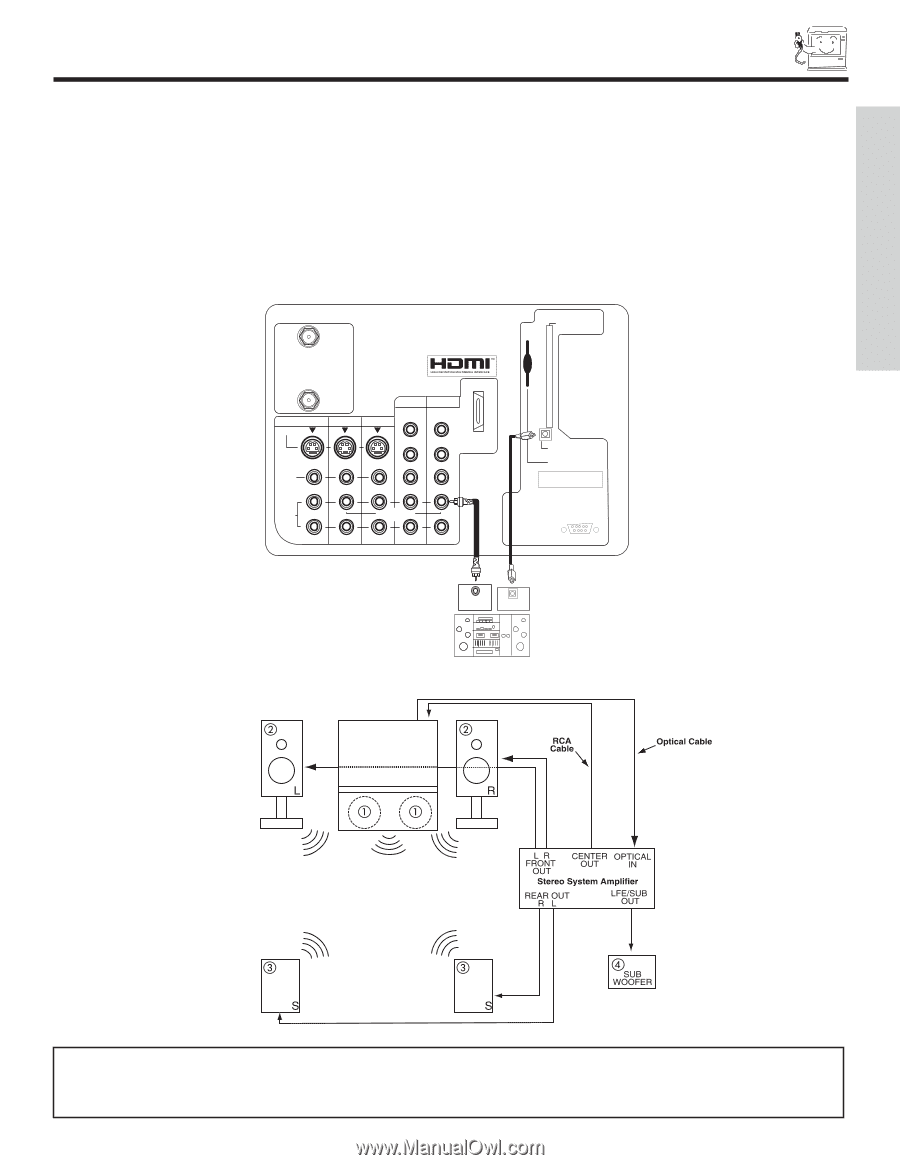
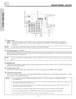
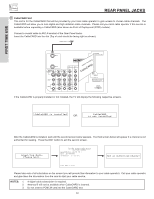
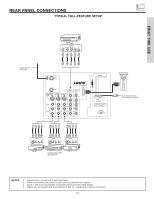
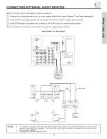
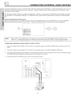
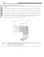
FIRST TIME USE CONNECTING EXTERNAL AUDIO DEVICES Match the numbers below to the diagram for speaker placement. ᕃ The television's internal speakers will act as center speaker (select Audio-Internal Speakers-TV as Center see page 49). ᕄ These FRONT left and right speakers are connected to the FRONT output of a separate audio amplifier. ᕅ These REAR left and right speakers are connected to the REAR output of a separate audio amplifier. ᕆ This subwoofer is connected to the LFE/Sub Out output of a separate audio amplifier. REAR PANEL OF TELEVISION ANT A ANT B MONITOR OUT S-VIDEO INPUT 4 INPUT 3 INPUT 2 Y/ VIDEO PB INPUT 1 Y/ VIDEO PB HDMI 1 VIDEO L AUDIO R AUDIO TO HI-FI PR PR (MONO) (MONO) (MONO) (MONO) TV AS CENTER CableCARD (Top of card faces right) OPTICAL OUT Digital Audio Upgrade Card Apparatus Claims of U.S. Patent Nos. 4,631,603; 4,577,216; 4,819,098; 4,907,093; and 6,381,747 licensed for limited viewing uses only. RS232C 1 2 345 6 789 CENTER OUT OPTICAL INPUT Stereo System Amplifier or DVD Player NOTES: 1. The Optical Out (Digital Audio) provides a fixed digital audio output to your external component such as an A/V receiver with optical input capability. The audio level can only be controlled through the volume control of the external audio amplifier. 2. See page 50 for AUDIO-Digital Output. 15
-
 1
1 -
2
-
3
-
4
-
5
-
6
-
7
-
8
-
9
-
 10
10 -
 11
11 -
 12
12 -
 13
13 -
 14
14 -
 15
15 -
 16
16 -
 17
17 -
 18
18 -
 19
19 -
 20
20 -
21
-
22
-
23
-
24
-
25
-
26
-
27
-
28
-
29
-
30
-
31
-
32
-
33
-
34
-
35
-
36
-
37
-
38
-
39
-
40
-
41
-
42
-
43
-
44
-
45
-
46
-
47
-
48
-
49
-
50
-
51
-
52
-
53
-
54
-
55
-
56
-
57
-
58
-
59
-
60
-
61
-
62
-
63
-
64
-
65
-
66
-
67
-
68
-
69
-
70
-
71
-
72
-
73
-
74
-
75
-
76
-
77
-
78
-
79
-
80
-
81
-
82
-
83
-
84
 |
 |