Hitachi C10RA3 Instruction Manual - Page 13
Anti-kickback Pawl - table saw
 |
UPC - 717709011038
View all Hitachi C10RA3 manuals
Add to My Manuals
Save this manual to your list of manuals |
Page 13 highlights
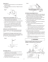
WARNING Improper splitter alignment can cause "kickback" and serious injury Fig. I Anti-kickback Pawl 8 10 9 Straight edge ADJUSTING THE 90°(00) AND 45° POSITIVE STOPS (FIG. J, K, L) Your saw has positive stops that will quickly position the saw blade at 90°(00) and 450 to the table. Make adjustments only if necessary. 90°(00) Stop 1. Disconnect the saw from the power source. 2. Turn the blade elevation handwheel and raise the blade to the maximum elevation. 3. Loosen the blade bevel lock knob (1) and move the blade to the maximum vertical position, then tighten the lock knob (1). 4. Place a combination square on the table and against the blade (2) to determine if the blade is 90°(00) to the table. (Fig. K) 5. If the blade is not 90°(00) to the table, loosen the two set screws (4), located on the collar (5) underneath the table saw (Fig. L) with the hex key, and back off the collar. 6. Loosen the bevel lock knob, turn the blade tilting handwheel to move the blade until it is 90°(00) to the table and tighten the bevel lock knob. 7. Adjust the collar (5) so it contacts the bracket (3) when the blade is 90°(00) to the table. Tighten the two set screws (4). (Fig.L) Fig. J 1 Fig. K 900 (00) English 450 2 45° Stop 1. With the blade in the upright 90°(00) position, loosen the bevel lock knob and move the blade to the maximum bevel angle. 2. Place the combination square on the table as shown in Fig. K to check if the blade is 45° to the table. 3. If the blade is not 45° to the table, loosen the two set screws (4), located on the collar (5) nuderneath the table saw, with the hex key, and back off the collar. (Fig. L) 4. Loosen the bevel lock knob, turn the blade tilting handwheel to move the blade until it is 45° to the table and tighten the blade bevel lock knob. 5. Adjust the collar (5) so it contacts the bracket (3) when the blade is 45° to the table. Tighten the two set screws. BLADE TILT POINTER 1. When the blade is positioned at 90°(00), adjust the blade tilt pointer to read 0° on the scale. 2. Loosen the mounting screw, position pointer over 0° and tighten the screw. NOTE: Make a trial cut on scrap wood before making critical cuts. Measure for exactness. Fig. L 4 3 5 3 450 4 900(00) 5 - 13 -
-
 1
1 -
2
-
3
-
4
-
5
-
6
-
7
-
 8
8 -
 9
9 -
 10
10 -
 11
11 -
 12
12 -
 13
13 -
 14
14 -
 15
15 -
 16
16 -
 17
17 -
 18
18 -
19
-
20
-
21
-
22
-
23
-
24
-
25
-
26
-
27
-
28
-
29
-
30
-
31
-
32
-
33
-
34
-
35
-
36
-
37
-
38
-
39
-
40
-
41
-
42
-
43
-
44
-
45
-
46
-
47
-
48
-
49
-
50
-
51
-
52
-
53
-
54
-
55
-
56
-
57
-
58
-
59
-
60
-
61
-
62
-
63
-
64
-
65
-
66
-
67
-
68
-
69
-
70
-
71
-
72
 |
 |
