Hitachi C10RA3 Instruction Manual - Page 14
and lock ruler so it holds its position in the square - rip fence
 |
UPC - 717709011038
View all Hitachi C10RA3 manuals
Add to My Manuals
Save this manual to your list of manuals |
Page 14 highlights
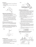
BLADE PARALLEL TO THE MITER GAUGE GROOVE (FIG. M, N) WARNING To avoid injury from an accidental start, make sure the switch is in the OFF position and the plug is disconnected from the power source outlet. This adjustment was made at the factory, but it should be rechecked and adjusted if necessary. This adjustment must be correct or kickback could result in a serious injury and accurate cuts can not be made. 1. Remove the safety switch key and unplug the saw. 2. Remove the blade guard for this procedure but reinstall and realign after adjustment. 3. Raise the blade to the heighest position and set at the 0° angle (900 straight up) 4. Select and mark with a felt tip marker, a blade tooth having a "right set" and rotate the blade so the marked tooth is 1/2 in. Above the table. 5. Place the combination square base (1) into the right side miter gauge groove (2). (Fig.M) 6. Adjust the ruler so it touches the front marked tooth and lock ruler so it holds its position in the square assembly. 7. Rotate the blade to the rear of the saw bringing the marked tooth approximately ½" above the blade. 8. Carefully slide the combination square to the rear until the ruler touches the marked tooth. 9. If the ruler touches the marked tooth at the front and rear position, no adjustment is needed at this time. If not or the base of the miter gauge groove, perform adjustment procedure described in next section. Fig. M 2 counterclockwise, then adjust the right side screw(3) clockwise. 2. Remeasure, as described in steps 4 to 9 in the prior section 3. When alignment is achieved, turn the left screw (2) nutil it touches the pivot rod (4) then tighten both nuts (1). If the blade is partial to left side: 4. Loosen the two nuts (1) and tighten the left screw (3) counterclockwise, then adjust the left side screw (2) clockwise. 5. Remeasure, as described in steps 4 to 9 in the prior section. 6. When alignment is achievde, turn the right screw (3) nutil it touches the pivot rod (4) then tighten both nuts (1). Fig. N 2 1 4 1 3 STORAGE (FIG. O, P) Rip fence and miter gauge (Fig. O) Storage brackets for the rip fence (2) and miter gauge (3) are located on the left side of the saw housing. Fig. O 2 3 1 Cord wrap (Fig. O-1) WARNING Do not wrap the cord around the dust port. Additional Blade Adjustments (Fig. N) NOTE: The adjusting nuts are 8 mm. The adjusting mechanism is located above the blade height adjusting hand wheel nuder the tabletop. If the front and rear measurments are not the same. Fig. O-1 If the blade is partial to right side: 1. Loosen the two nuts (1) and turn the left screw (2) - 14 -
-
 1
1 -
2
-
3
-
4
-
5
-
6
-
7
-
8
-
 9
9 -
 10
10 -
 11
11 -
 12
12 -
 13
13 -
 14
14 -
 15
15 -
 16
16 -
 17
17 -
 18
18 -
 19
19 -
20
-
21
-
22
-
23
-
24
-
25
-
26
-
27
-
28
-
29
-
30
-
31
-
32
-
33
-
34
-
35
-
36
-
37
-
38
-
39
-
40
-
41
-
42
-
43
-
44
-
45
-
46
-
47
-
48
-
49
-
50
-
51
-
52
-
53
-
54
-
55
-
56
-
57
-
58
-
59
-
60
-
61
-
62
-
63
-
64
-
65
-
66
-
67
-
68
-
69
-
70
-
71
-
72
 |
 |
