Hitachi C10RA3 Instruction Manual - Page 15
Position the fence on the right side of the table, - blade replacement
 |
UPC - 717709011038
View all Hitachi C10RA3 manuals
Add to My Manuals
Save this manual to your list of manuals |
Page 15 highlights
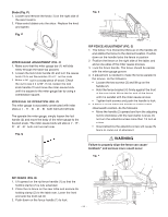
Blade (Fig. P) 1. Loosen and remove the knob (1) on the right side of the saw housing. 2. Place extra blades onto the arbor. Replace the knob and tighten. Fig. P 1 MITER GAUGE ADJUSTMENT (FIG. Q) 1. Make sure that the miter gauge bar (1) will slide freely through the table top grooves. 2. Loosen the lock knob handle (2) and turn the gauge body (3) to set the pointer (4) at 0º on the scale. 3. Make a 90º cut in a scrap piece of wood. Check the cut to see if it is 90º. If not, loosen the lock knob handle (2) and move the miter gauge body until it is square to the miter gauge bar by using a combination square. MITER GAUGE OPERATION (FIG. Q) The miter gauge is accurately constructed with index stops at 0º, 15º, 30º, 45º, 60º both right and left side. The operate the miter gauge, simply loosen the lock handle (2) and move the body of the miter gauge to the desired angle. The miter gauge body will stop at 0º, 15º, 30º, 45º, 60º both right and left side. Fig. Q 1 60 4 45 45 30 15 0 15 30 60 3 2 Fig. R 2 3 1 RIP FENCE ADJUSTMENT (FIG. S) 1. The fence (1) is moved by lifting up on the handle (2) and sliding the fence to the desired location. Pushing down on the handle locks the fence in position. 2. Position the fence on the right side of the table, and along one edge of the miter gauge grooves. 3. Lock the fence handle. The fence should be parallel with the miter gauge groove. 4. If adjustment is needed to make the fence parallel to the groove, do the following: • Loosen the two screws (3) and lift up on the handle (2). • Hold the fence bracket (4) firmly against the front of the saw table. Move the far end of the fence until it is parallel with the miter gauge groove. • Tighten both screws and push the handle to lock. 5. If fence is loose when the handle is in the locked (downward) position, do the following: • Move the handle (2) upward and turn the adjusting nut (5) clockwise until the rear clamp is snug. Do not turn the adjusting screw more than 1/4 turn at a time. • Over-tightening the adjusting screw will cause the fence to come out of alignment. WARNING Failure to properly align the fence can cause " kickback" and serious injury could occur. Fig. S 5 1 3 RIP FENCE (FIG. R) 1. Lift upward on the rip fence handle (1) so that the holding clamp (2) is fully extended. 2. Place the rip fence on the saw table and engage the holding clamp (2) to the table rear. Lower the front end onto the front rail (3). 3. Push down on the fence handle (1) to lock. - 15 - 4 2
-
 1
1 -
2
-
3
-
4
-
5
-
6
-
7
-
8
-
9
-
 10
10 -
 11
11 -
 12
12 -
 13
13 -
 14
14 -
 15
15 -
 16
16 -
 17
17 -
 18
18 -
 19
19 -
 20
20 -
21
-
22
-
23
-
24
-
25
-
26
-
27
-
28
-
29
-
30
-
31
-
32
-
33
-
34
-
35
-
36
-
37
-
38
-
39
-
40
-
41
-
42
-
43
-
44
-
45
-
46
-
47
-
48
-
49
-
50
-
51
-
52
-
53
-
54
-
55
-
56
-
57
-
58
-
59
-
60
-
61
-
62
-
63
-
64
-
65
-
66
-
67
-
68
-
69
-
70
-
71
-
72
 |
 |
