Honeywell HPF24S6 Installation Manual
Honeywell HPF24S6 Manual
 |
View all Honeywell HPF24S6 manuals
Add to My Manuals
Save this manual to your list of manuals |
Honeywell HPF24S6 manual content summary:
- Honeywell HPF24S6 | Installation Manual - Page 1
HPF24S6 & HPF24S8, HPF24S6E & HPF24S8E, HPF24S6C & HPF24S8C FIELD CHARGER/POWER SUPPLY INSTALLATION MANUAL P/N 52751:F2 • ECN 14-570 • 7/11/2014 - Honeywell HPF24S6 | Installation Manual - Page 2
detectors, manual pull stations Guide for Proper Use of System Smoke Detectors, which is made available at no charge to all installing and instruct them for service with your installers only. Adequate written records of all inspections should be kept. Limit-D-1-2013 2 HPF24S Series Power Supplies - Honeywell HPF24S6 | Installation Manual - Page 3
problem-free installation with long-term reliability: WARNING - Several different sources of power can be connected to the fire alarm control panel. Disconnect all sources of power before servicing and if not installed and used in accordance with the instruction manual may cause interference to - Honeywell HPF24S6 | Installation Manual - Page 4
for how to correct/improve documentation Send email messages to: [email protected] Please note this email address is for documentation feedback only. If you have any technical issues, please contact Technical Services. 4 HPF24S Series Power Supplies - P/N 52751:F2 7/11/2014 - Honeywell HPF24S6 | Installation Manual - Page 5
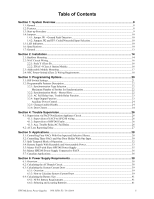
...10 1.7: General...13 Section 2: Installation...14 2.1: Backbox Mounting ...14 2.2: Supply With Resettable and Nonresettable Power 33 5.5: Master FACP with Slave HPF24S Power Supply 35 5.6: Master HPF24S Power Supply Connected to FACP 36 5.7: Canadian Applications...36 Section 6: Power Supply - Honeywell HPF24S6 | Installation Manual - Page 6
Table of Contents Appendix A: Wire Requirements 43 Index ...44 6 HPF24S Series Power Supplies - P/N 52751:F2 7/11/2014 - Honeywell HPF24S6 | Installation Manual - Page 7
Impaired UL 2572 Standard for Mass Notification Systems CAN/ULC - S524-01 Standard for Installation of Fire Alarm Systems CAN/ULC-S527-99 Standard for Control Units for Fire Alarm approval of the local Authority Having Jurisdiction (AHJ). HPF24S Series Power Supplies - P/N 52751:F2 7/11/2014 7 - Honeywell HPF24S6 | Installation Manual - Page 8
or 24 VDC power source. The power supplies are compatible with 12 VDC and 24 VDC control panels. The HPF24S6E and HPF24S8E offer the same features as the HPF24S6 and HPF24S8 respectively but allow connection to 220/240 VAC. Unless otherwise specified, the information in this manual applies to both - Honeywell HPF24S6 | Installation Manual - Page 9
as described in "Jumpers" on page 10. 2. Install the power supply as described in"Installation" on page 14. 3. Program the power supply as described in "Programming Options" on page 20. 4. Wire the power supply circuits, referring to the options described in"Trouble Supervision" on page 26 and the - Honeywell HPF24S6 | Installation Manual - Page 10
the top right section of the power supply circuit board. JP2 is used for problem, only the Charger Trouble/AC Loss LED will turn on. 1.6 Specifications Refer to Figure 1.1 on page 12 for terminal locations. Primary AC Power - TB1 • HPF24S6(C) & HPF24S8(C): 120 VAC, 60 Hz, 3.2 amps maximum • HPF24S6E - Honeywell HPF24S6 | Installation Manual - Page 11
, nonpower-limited • Supports lead acid type batteries only • Float Charge Voltage: 27.6 VDC • Maximum Charge Current: 1.5 A • Battery fuse (F1) 15A, 32V (Canadian version is nonreplaceable 12A, 32V) • Maximum Battery Capacity: 18.0 AH • Minimum Battery Capacity: 7.0 AH • Power supply draws maximum - Honeywell HPF24S6 | Installation Manual - Page 12
+ Aux. 24 VDC* - Control Input 2 + Control Input 2 - Out Common + Out/Trouble Contact - Control Input 1 + Control Input 1 - Sync Input + Sync Input *Note: Auxiliary Power Output is power-limited (Class 2) but not supervised 24fs8brd.wmf 12 HPF24S Series Power Supplies - P/N 52751:F2 7/11/2014 - Honeywell HPF24S6 | Installation Manual - Page 13
supervises its NAC field wiring for short and open conditions. If a fault is detected, the power supply will enter a trouble condition and illuminate the NAC Trouble LED. When the NACs are activated, the supervision is disabled and the circuits are no longer supervised (except for short circuit - Honeywell HPF24S6 | Installation Manual - Page 14
is in a clean, dry, vibration-free area where extreme temperatures are not encountered. The area should be readily accessible with sufficient room to easily install and maintain the power supply. With the hinge mounting on the left, determine the number of conductors required for the devices to be - Honeywell HPF24S6 | Installation Manual - Page 15
Backbox Mounting Installation 2.875" (7.3 cm) 0.75" (1.9 cm) Height=15.00" (38.10 cm) 10.625" (26.99 cm) Top Backbox = 14.5" cm) Backbox Mounting Holes Bottom 1.125" (2.868 cm) Figure 2.2 Backbox Mounting Dimensions fcpscabb.wmf HPF24S Series Power Supplies - P/N 52751:F2 7/11/2014 15 - Honeywell HPF24S6 | Installation Manual - Page 16
Installation 2.2 NAC HPF24S6 or HPF24S8 to support Style Z (Class A) Notification Appliance Circuits. ZNAC-4 Option Module ZNAC-4 Horn Strobes Alarm Polarity Shown 24fsclsa.wmf J3 HPF24S Circuit Board Figure 2.4 Style Z (Class A) NACs using ZNAC-4 Option Module 16 HPF24S Series Power Supplies - Honeywell HPF24S6 | Installation Manual - Page 17
is required to install an addressable module on the power supply main circuit board. The kit includes four female/female and four male/female standoffs as well as four mounting screws. *If the SLC device does not match the one in this figure, refer to the SLC manual - Honeywell HPF24S6 | Installation Manual - Page 18
Circuits (Class 2) *If the SLC device does not match the one in this figure, refer to the SLC manual wiring conversion charts for legacy and newer versions of the modules. Figure 2.5 Power-limited (Class 2) Wiring Example 24fspwrltpH.wmf 18 HPF24S Series Power Supplies - P/N 52751:F2 7/11/2014 - Honeywell HPF24S6 | Installation Manual - Page 19
Notes HPF24S Series Power Supplies - P/N 52751:F2 7/11/2014 19 - Honeywell HPF24S6 | Installation Manual - Page 20
OFF positions. Important: Change DIP switch settings only when all power (AC & DC) is removed. Switches 1 through 7 shown in OFF (Open) position Switch 8 shown in ON (Closed) position Figure 3.1 Field Programming DIP Switches 24fsswitc.wmf 20 HPF24S Series Power Supplies - P/N 52751:F2 7/11/2014 - Honeywell HPF24S6 | Installation Manual - Page 21
Trouble Relay responds to all troubles Internal Trouble contact responds to AC loss No Delay in AC Fail Reporting Aux. Trouble Relay responds only to AC Fail/Brownout Internal Trouble Input is ignored. 4 When using Split Alarm with power supply configured for Slave Mode, System Sensor cannot be used - Honeywell HPF24S6 | Installation Manual - Page 22
Sensor Wheelock Gentex HPF24S6 (max. strobes) 51 30 39 HPF24S8 (max. strobes) 51 40 39 3.2.2 Synchronization Mode - Master/Slave The HPF24S power supply can be configured for Master or Slave Synchronization by setting DIP switch 3 ON for Slave or OFF for Master mode. In some installations, it is - Honeywell HPF24S6 | Installation Manual - Page 23
. • DIP switch 4 set to the ON position will delay the generation of an AC Loss/brownout trouble signal for 2 hours. In addition, the Aux. Trouble Relay will immediately respond to all trouble conditions on the power supply. • DIP switch 4 set to the OFF position will allow the HPF24S to generate - Honeywell HPF24S6 | Installation Manual - Page 24
input is ignored for Output 4. 2 If no synchronization is selected by switches 1 & 2, the Sync Input is ignored. 3 When using Split Alarm with power supply configured for Slave Mode, System Sensor cannot be used (use System Sensor with Master Mode only). 4 Selective Silence allows the silencing of - Honeywell HPF24S6 | Installation Manual - Page 25
Notes HPF24S Series Power Supplies - P/N 52751:F2 7/11/2014 25 - Honeywell HPF24S6 | Installation Manual - Page 26
Input Circuit #2 Terminals 7 & 8, the ELR must be installed after the last device on the circuit. 4.1.2 Supervision of HPF24S Faults The FACP will detect HPF24S power supply faults as an open circuit condition on its NAC. An internal trouble contact is located between TB4 Terminal 3 (In+) and TB4 - Honeywell HPF24S6 | Installation Manual - Page 27
A ground fault condition on the power supply (zero impedance between the power supply and ground - A field wiring fault on the NAC output of the power supply. (If the panel is in alarm, only a short circuit on the NAC will be detected as a trouble) NOTE: The NAC Trouble LED will indicate which NAC - Honeywell HPF24S6 | Installation Manual - Page 28
5.1 Controlling Four NACs With One Input and Selective Silence NOTE: The Relay Module is required only for this application with the power supply set as Master. If the power supply is set as Slave, the Relay Module is not required. In Slave mode, selective silence (horn mute) is provided by the - Honeywell HPF24S6 | Installation Manual - Page 29
manual wiring conversion charts for legacy and newer versions of the modules. EOLR-1 (energized) Figure 5.1 Controlling Four Outputs With One Input The following notes apply to Figure 5.1 on page 29. 1. When the HPF-24S power supply is in an inactive state (control module not active), a trouble - Honeywell HPF24S6 | Installation Manual - Page 30
& 10 with an EOL relay (P/N: EOLR-1). 6. For a list of compatible devices, refer to the HPP Device Compatibility Document #54399. 7. IMPORTANT! When the power supply is programmed for both Selective Silence and Slave Mode, TB4 Terminal 7 (IN+) must be jumpered to Terminal 9 (AUX+) and Terminal 8 (IN - Honeywell HPF24S6 | Installation Manual - Page 31
figure, refer to the SLC manual wiring conversion charts for legacy and trouble contacts at TB5 of the power supply can also be used for independent trouble monitoring. 3. Do not loop wires under screw terminals. Break wires to maintain proper supervision. 4. An End-of-Line Resistor must be installed - Honeywell HPF24S6 | Installation Manual - Page 32
IN SYNC IN + TB4 Internal Trouble Contact HPF24S ZNAC-4 Option Module End-of-Line Resistor supplied with Control Module 1 2 manual wiring conversion charts for legacy and newer versions of the modules. Figure 5.3 Split Temporal Mode Application 24fsapp5tpH2.wmf 32 HPF24S Series Power Supplies - Honeywell HPF24S6 | Installation Manual - Page 33
5 & 6). As an alternative, the trouble contacts at TB5 of the power supply can also be used for independent trouble monitoring. 2. Do not loop wires under screw terminals. Break wires to maintain proper supervision. 3. An End-of-Line Resistor must be installed between terminals 5 & 6 for control - Honeywell HPF24S6 | Installation Manual - Page 34
the SLC SLC manual wiring conversion charts for legacy and newer versions of the modules. 24fsapp4tpH.wmf Figure 5.4 Remote Power Supply Application The following notes apply to Figure 5.4 on page 34. 1. An End-of-Line Resistor must be installed between TB5, Terminal 1 (trouble relay common) and - Honeywell HPF24S6 | Installation Manual - Page 35
to a master FACP programmed for synchronized output. The power supply should be set for synchronization which matches the FACP programming. Standby Polarity Shown FACP See Note 3 - NAC1 (programmed for sync) + Internal Trouble Contact HPF24S 1 2 3 4 5 6 7 8 9 10 ELR OUT4 OUT3 OUT2 OUT1 - Honeywell HPF24S6 | Installation Manual - Page 36
Connected to FACP In this application, a master HPF24S power supply, set for synchronization, is connected to an FACP with nonsynchronized output. Standby Polarity Shown FACP NAC with no syncronization - NAC1 + Internal Trouble Contact HPF24S 1 2 3 4 5 6 7 8 9 10 ELR for FACP NAC OUT4 OUT3 - Honeywell HPF24S6 | Installation Manual - Page 37
Applications NAC Outputs only Cut JP1 Applications 24fsCanadiantpH.wmf Battery - Battery - HPF24S Power Supply Host FACP *If the SLC device does not match the one in this figure, refer to the SLC manual wiring conversion charts for legacy and newer versions of the modules. HPF24S Series - Honeywell HPF24S6 | Installation Manual - Page 38
section contains instructions and tables for calculating power supply currents in alarm and standby conditions. This is a four-step process, consisting of the following: 1. Calculating the total amount of AC branch circuit current required to operate the system 2. Calculating the power supply load - Honeywell HPF24S6 | Installation Manual - Page 39
during the non-fire alarm condition. To calculate the non-fire alarm load on the power supply when primary power is applied, use Calculation Column 1 in Table 6.3 on page 40. The power supply must support a larger load current during a fire alarm condition. To calculate the fire alarm load on the - Honeywell HPF24S6 | Installation Manual - Page 40
Power Supply Requirements Calculating the System Current Draw Table 6.3 contains three columns 0.025] = [ ]= Sum each column for totals Primary Non-Alarm = Primary Alarm = Secondary Alarm = Table 6.3 System Current Draw Calculations 40 HPF24S Series Power Supplies - P/N 52751:F2 7/11/2014 - Honeywell HPF24S6 | Installation Manual - Page 41
total Standby and Alarm load in ampere hours (AH). This total load determines the battery size (in AH) required to support the power supply under the loss of AC power. Complete Table 6.4 as follows: 1. Enter the totals from Table 6.3 on page 40, Calculation Columns 2 and 3 where shown. 2. Enter the - Honeywell HPF24S6 | Installation Manual - Page 42
Notes 42 HPF24S Series Power Supplies - P/N 52751:F2 7/11/2014 - Honeywell HPF24S6 | Installation Manual - Page 43
the correct type of wire, gauge and run length for each circuit. The following table lists NAC wiring requirements for the HPF24S6 and HPF24S8 Field Charger Power Supply. NAC Load (Amps) Max. allowable total loop resistance (ohms) CLASS-B Max. allowable wire pair lenth (feet) AWG 12 AWG 14 AWG - Honeywell HPF24S6 | Installation Manual - Page 44
Resistor 26 End-of-Line Resistor see also ELR 26 F faults 26 Features 8 filtered power 8 float charge voltage 11 Form-C see also Relay 9 G ground fault 8 ground fault detection 9, 10 Jumper JP1 10 ground fault LED 10 H HPF24S6 8 HPF24S8 8 44 HPF24S Series Power Supplies - P/N 52751:F2 7/11/2014 - Honeywell HPF24S6 | Installation Manual - Page 45
NAC output 11 Style 11 voltage rating 11 output power 8 P Power nonresettable 8 resettable 8 power supply board layout drawing 12 connectors and jumpers 12 power supply requirements 38 powering supply 38 power-limited 8 power-limited wiring 18 R relay trouble 8, 9, 11, 26 reporting delay AC loss 27 - Honeywell HPF24S6 | Installation Manual - Page 46
W-Z trouble relay 8, 9, 11, 26 contact rating 11 trouble supervision 8 troubles 26 power supply 8 W wiring 9 AC power 10 power-limited 18 Z ZNAC-4 16 see also Class A Converter Module 8 Index 46 HPF24S Series Power Supplies - P/N 52751:F2 7/11/2014 - Honeywell HPF24S6 | Installation Manual - Page 47
HPF24S Series Power Supplies - P/N 52751:F2 7/11/2014 47 - Honeywell HPF24S6 | Installation Manual - Page 48
Automation and Control Solutions Honeywell Power Products 12 Clintonville Road Northford, CT 06472-1610 www.honeywellpower.com ® U.S. Registered Trademark © 2014 Honeywell International Inc. 52751 F2. Rev. 07-14
-
 1
1 -
 2
2 -
 3
3 -
 4
4 -
 5
5 -
 6
6 -
 7
7 -
8
-
9
-
10
-
11
-
12
-
13
-
14
-
15
-
16
-
17
-
18
-
19
-
20
-
21
-
22
-
23
-
24
-
25
-
26
-
27
-
28
-
29
-
30
-
31
-
32
-
33
-
34
-
35
-
36
-
37
-
38
-
39
-
40
-
41
-
42
-
43
-
44
-
45
-
46
-
47
-
48
 |
 |

INSTALLATION MANUAL
HPF24S6 & HPF24S8, HPF24S6E &
HPF24S8E, HPF24S6C & HPF24S8C
FIELD CHARGER/POWER SUPPLY
P/N 52751:F2 • ECN 14-570 • 7/11/2014