Icom IC-7000 Service Manual - Page 11
Drive And Power Amplifier Circuits, Pa And Driver Units, 2-10 Alc Circuit Main Unit, Tx/rx Switch D406 - hf vhf uhf transceiver
 |
View all Icom IC-7000 manuals
Add to My Manuals
Save this manual to your list of manuals |
Page 11 highlights
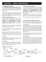
3-2-9 DRIVE AND POWER AMPLIFIER CIRCUITS (PA AND DRIVER UNITS) The drive and power amplifier circuits amplify the RF signal from the RF circuit (MAIN unit) to obtain 100 W of RF output power for the HF/50 MHz bands, 50 W for the VHF band and 35 W for the UHF band. The RF signal from the MAIN unit is applied to the pre drive amplifiers (PA unit; Q101, Q102) after passed through the attenuator (PA unit; R101-R103). The amplified signal is applied to the drive amplifier (DRIVER unit; Q504) to amplify a level needed for the power amplifiers. The amplified HF/50 MHz bands signal from the drive amplifier is amplified at the power amplifiers (PA unit; Q301, Q302) to obtain a stable 100 W of RF output power. The power amplified signal is passed through the TX/RX switch (RL801), one of the 7 low-pass filters, APC detector (PA unit; D961, D962) and then applied to the [ANT1] connector (CHASSIS; J1). The amplified VHF RF signal from the drive amplifier is amplified at the power amplifier (Q501) to obtain a stable 50 W of RF output power. The power amplified signals are applied to the low-pass filter, APC detector (D501-D504), TX/RX switch (D506, D510), low-pass filters (L506, L508, L510, L601-L603, C516, C519, C521, C601, C602) and [ANT2] connector (CHASSIS; J2). The amplified UHF RF signal from the drive amplifier is amplified at the power amplifier (Q401) to obtain a stable 35 W of RF output power. The power amplified signal is applied to the low-pass filter, APC detector (D401-D404), TX/RX switch (D406, D407), high-pass filter (L413, L414, C428, C429, C431, C433), low-pass filter (L601-L603, C601, C602) and [ANT2] connector (CHASSIS; J2). 3-2-10 ALC CIRCUIT (MAIN UNIT) The ALC (Automatic Level Control) circuit reduces the gain of IF amplifiers in order for the transceiver to output a constant RF power set by the RF power setting even when the supplied voltage shifts, etc. The HF/50 MHz power amplified signal from the power amplifiers (PA unit; Q301, Q302) is detected at the APC detector (PA unit; D961). The detected voltage is applied to the buffer amplifier (PA unit; IC960, pins 5, 7) and then applied to the MAIN unit as the "HFOR" voltage. The VHF and UHF RF power amplified signal from the power amplifiers (PA unit; Q401, Q501) are detected at the APC detectors (PA unit; D401, D404, D501, D504) respectively. The detected voltages ("VFOR" and "UFOR") are combined to "VUFOR" voltage and then applied to the MAIN unit. The "HFOR" and "VUFOR" voltages are combined to the "FORL" voltage and then applied to the ALC amplifier (IC1601, pins 1, 2). The "POCV" voltage from the D/A converter (IC2155, pin 19) via the buffer amplifier (IC2101, pins 5, 7), determined by the RF power setting, is applied to the ALC amplifier (IC1601, pin 3) as the reference voltage. When the "FORL" voltage exceeds the "POCV" voltage, ALC bias voltage from IC1601 (pin 1) controls the IF amplifiers (Q701, Q901). This adjusts the output power to the level determined by the RF power setting until the "FORL" and "POCV" voltages are equalized. In AM mode, IC1601 functions as an averaging ALC amplifier with Q1601. The AM switch (Q1602) is turn ON and shifts the "POCV" voltage to adjust the TX output power for the AM mode (maximum; 40 W for HF/50 MHz bands, 20 W for VHF band, 14 W for UHF band). The ALC bias voltage from IC1601 is also applied to the main CPU (LOGIC unit; IC1302, pin 115) as the "ALCL" voltage for ALC meter indication. The external ALC input (negative voltage) from the [ACC] socket (pin 6) is converted to a positive voltage at D1609 and is applied to the buffer amplifier (Q1604). External ALC operation is identical to that of the internal ALC. 3-2-11 APC CIRCUIT (MAIN UNIT) The APC (Automatic Power Control) circuit protects the power amplifiers on the PA unit from high SWR and excessive current. The reflected wave signal appears and increases on the antenna connector when the antenna is mismatched. The HF/50 MHz reflected signal level is detected at D962 (PA unit), and is amplified at the buffer amplifier (PA unit; IC960, pins 1, 3) and applied to the ALC amplifier (IC1601, pins 8, 9) as the "HREF" voltage. • ALC CIRCUIT 3rd mixer TX signals IF Q901 2nd mixer IF Q701 1st mixer Crystal BPF FI601 HPFs BPF AMP DRIVER UNIT ALC amplifier ALC 1 ALC 2 IC1601 PA UNIT HF/50 MHz PA LPFs 145 MHz PA 430 MHz PA APC DET APC DET APC DET ANT1 ANT2 3 - 6
-
 1
1 -
2
-
3
-
4
-
5
-
 6
6 -
 7
7 -
 8
8 -
 9
9 -
 10
10 -
 11
11 -
 12
12 -
 13
13 -
 14
14 -
 15
15 -
 16
16 -
17
-
18
-
19
-
20
-
21
-
22
-
23
-
24
-
25
-
26
-
27
-
28
-
29
-
30
-
31
-
32
-
33
-
34
-
35
-
36
-
37
-
38
-
39
-
40
-
41
-
42
-
43
-
44
-
45
-
46
-
47
-
48
-
49
-
50
-
51
-
52
-
53
-
54
-
55
-
56
-
57
-
58
-
59
-
60
-
61
-
62
-
63
-
64
-
65
-
66
-
67
-
68
-
69
-
70
-
71
-
72
-
73
-
74
-
75
-
76
-
77
-
78
-
79
-
80
-
81
-
82
-
83
-
84
-
85
-
86
-
87
-
88
-
89
-
90
-
91
-
92
 |
 |
