Icom IC-7000 Service Manual - Page 7
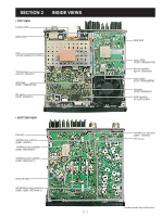
1st If Circuit Main Unit
 |
View all Icom IC-7000 manuals
Add to My Manuals
Save this manual to your list of manuals |
Page 7 highlights
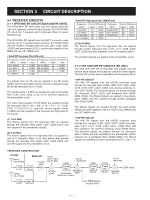
The amplified signals are passed through the band switch (D461) and then applied to the 1st mixer circuit (MAIN unit) via J101 (MAIN unit). D453-D456, D553, D554, D556 and D558-D560 are varactor diodes that tune the center frequency of an RF passband for wide bandwidth receiving and good image response rejection. When receiving the signals, higher than 129 MHz, are received, the switching diodes (D555, D557) are turned off by the control signal "2MBL" from the CPU (LOGIC unit; IC1302) via Q2150, then the varactor diodes (D556, D558) are disconnected to shift the filtering frequencies. 3-1-3 PREAMPLIFIER CIRCUIT (MAIN UNIT) The preamplifier circuit amplifies received RF signals for wide band frequency range. When the preamplifier is turned ON, the RF signals (HF/50 MHz bands) from the high-pass filters are applied to the preamplifier (Q301) via the preamplifier switches (D301, D302). When the preamplifier is turned OFF, the RF signals (HF/50 MHz bands) are passed through the bypass switches (D301, D303). The amplified or bypassed signals are applied to the 1st mixer circuit (IC401). 3-1-4 1ST MIXER CIRCUIT (MAIN UNIT) The 1st mixer circuit mixes the received RF signals with the 1st LO signal to convert the receive signal frequencies to the 1st IF frequency. While receiving the HF/50 MHz bands signals, the amplified signals from the preamplifier switch (D304) or the bypassed signals from the bypass switch (D303) are passed through the low-pass filter (L310, L312, C314, C316, C318, C320, C322) and then applied to the 1st mixer circuit (IC401) via the band switch (D305). While receiving the VHF/UHF bands signals, the signals from the VHF/UHF RF circuit (PA unit) are passed through the low-pass filter (L309, L311, L313, C313, C315, C317, C319, C321, C323, C325) and then applied to the 1st mixer circuit (IC401) via the band switch (D306). The applied signals are mixed with the 1st LO signal (124.517 -594.487 MHz) and convert into the 1st IF signal. The 1st LO signal is generated in the DDS unit, and applied to the 1st mixer circuit (IC401, pins 1, 6) after being amplified and attenuated at the 1st LO amplifier (IC421, pins 1, 4) and the attenuators (R416-R418, R421-R423), respectively. The converted 1st IF signal is applied to the 1st IF circuit. 3-1-5 1ST IF CIRCUIT (MAIN UNIT) The 1st IF circuit filters and amplifies the 1st IF signal. The converted 1st IF signal is • 1st IF frequency applied to the IF amplifier (Q502) Mode 1st IF via RX switches (D502, D505). USB 124.48850 MHz The 124.487 MHz 1st IF signal (except WFM mode) passes through the crystal filter (FI601) via the mode switches (D602, D604), and the 134.732 MHz 1st LSB 124.48550 MHz CW 124.48700 MHz RTTY 124.48683 MHz AM/FM 124.48700 MHz WFM 134.73200 MHz IF signal (WFM mode) passes through the bandpass filter (L607, L609, C602, C606, C608-C610, C617, C618) via the mode switches (D601, D603) to suppress out-of-band sig- nals. Then the filtered signal is applied to the IF amplifier (Q702) and then applied to the 2nd mixer circuit (D801) via the RX switches (D702, D704). 3-1-6 2ND MIXER CIRCUIT (MAIN UNIT) The 2nd mixer circuit mixes the 1st IF signal with the 2nd LO signal to convert into the 2nd IF frequency. The amplified signal from the IF amplifier (Q702) is applied to the 2nd mixer circuit (D801) and then mixed with the 2nd LO signal (124.032 MHz) to convert into the 455 kHz (other than WFM) or 10.7 MHz (WFM) 2nd IF signal. The 2nd LO signal is generated in the DDS unit, and applied to the 2nd mixer circuit (D801) after being filtered and attenuated at the low-pass filter (L808, C816, C817) and the attenuators (R801, R805, R806, R809-R811), respectively. The converted 2nd IF signal is applied to the 2nd IF circuit. 3-1-7 2ND IF CIRCUIT (MAIN UNIT) The 2nd IF circuit amplifies and filters the 2nd IF signal. The converted 2nd IF signal is applied to the bandpass filter (FI901) to suppress undesired signals. The 455 kHz 2nd IF signal (except • 2nd IF frequency WFM mode) is passed through the bandpass filter (FI901) via the mode switch (D803) and then amplified at the IF amplifier (Q902). The amplified signal is passed through the bandpass filter (FI1001) and then applied to another IF amplifier (Q1001). Mode USB LSB CW RTTY AM/FM WFM 2nd IF 456.500 kHz 453.500 kHz 455.000 kHz 454.830 kHz 455.000 kHz 10.700 MHz The amplified signal is applied to the 3rd mixer circuit. The 10.7 MHz 2nd IF signal for WFM mode is passed through the low-pass filter (L1402, C1402-C1404) via the mode switch (D802) and then applied to the IF amplifier (Q1401). The amplified signal is passed through the bandpass filter (FI1401) and then applied another IF amplifier (Q1402). 3 - 2
-
 1
1 -
 2
2 -
 3
3 -
 4
4 -
 5
5 -
 6
6 -
 7
7 -
 8
8 -
 9
9 -
 10
10 -
 11
11 -
 12
12 -
13
-
14
-
15
-
16
-
17
-
18
-
19
-
20
-
21
-
22
-
23
-
24
-
25
-
26
-
27
-
28
-
29
-
30
-
31
-
32
-
33
-
34
-
35
-
36
-
37
-
38
-
39
-
40
-
41
-
42
-
43
-
44
-
45
-
46
-
47
-
48
-
49
-
50
-
51
-
52
-
53
-
54
-
55
-
56
-
57
-
58
-
59
-
60
-
61
-
62
-
63
-
64
-
65
-
66
-
67
-
68
-
69
-
70
-
71
-
72
-
73
-
74
-
75
-
76
-
77
-
78
-
79
-
80
-
81
-
82
-
83
-
84
-
85
-
86
-
87
-
88
-
89
-
90
-
91
-
92
 |
 |
