Icom IC-7000 Service Manual - Page 8
3rd If Circuit Main Unit, 1-12 Af Amplifier Circuit Main Unit - amp noise
 |
View all Icom IC-7000 manuals
Add to My Manuals
Save this manual to your list of manuals |
Page 8 highlights
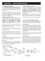
The amplified IF signal is passed through the bandpass filter (FI1402) and then applied to the WFM demodulator circuit (IC1401). 3-1-11 DSP CIRCUIT (LOGIC UNIT) The DSP (Digital Signal Processor) circuit enables digital IF filter, manual notch, digital twin PBT and phase demodulation, etc. 3-1-8 3RD MIXER CIRCUIT (MAIN UNIT) The 3rd mixer circuit mixes the 2nd IF signal with the 3rd LO signal to convert into the 3rd IF frequency. The amplified signal from the IF amplifier (Q1001) are mixed with the 3rd LO signal (438.85 kHz), where come from the DDS unit via J2406, at the 3rd mixer circuit (IC1101) to convert into the 16.15 kHz 3rd IF signal. The converted 3rd IF signal is applied to the 3rd IF circuit. The 3rd IF or demodulated AF (WFM mode) signals are passed through the low-pass filter (IC451, pins 1, 2) and then applied to the A/D converter (IC551, pin 4). The converted signals are applied to the DSP ICs (IC301, IC2201) for the digital IF filter, demodulation, automatic notch and noise reduction, etc. The output digital audio signals from the DSP IC (IC301) are applied to the D/A converter (IC551) to convert into the analog audio signals. 3-1-9 3RD IF CIRCUIT (MAIN UNIT) The 3rd IF circuit filters and amplifies the 3rd IF signal. The converted 3rd IF signal is amplified at the 3rd IF amplifier (IC1203, pins 5, 7) and then passed through the lowpass filter (IC1203, pins 1, 3). The filtered signal is passed through the mode switches (IC1201, pins 1, 7; IC1202, pins 1, 7) and then applied to the analog switch (IC1256, pins 11, 13). The converted audio signals from the D/A converter (IC551, pins 25, 26) are passed through the low-pass filter (IC601, pins 5-7), and then applied to the AF amplifier circuit (MAIN unit) via J701 (pin 14). 3-1-12 AF AMPLIFIER CIRCUIT (MAIN UNIT) The AF amplifier amplifies the demodulated AF signals to drive speaker. The switched signal is applied to the DSP circuit (LOGIC unit) via the J2251 (pin 1). The filtered signal from the low-pass filter (LOGIC unit; IC601, pins 5-7) are passed through another low-pass filter (IC2551, pins 1, 3). 3-1-10 DEMODULATOR CIRCUITS (MAIN UNIT) • WFM mode The demodulator circuit converts the 2nd IF signal into the AF signals. While in FM mode, the filtered AF signals from the low-pass filter (IC2551, pin 1) are applied to the de-emphasis circuit (IC2551, pins 5-7) to obtain the -6 dB/octave characteristics and then applied to the AF switch (IC2601, pins 1, 6). The filtered signal from the bandpass filter (FI1402) is applied to the IF amplifier section inside the WFM demodulator (IC1401, pin 1) and then applied to the quadrature detector section to convert into AF signals. The detected AF signals are output from pin 6 (IC1401) and then applied to the mode switches (IC1201, pins 1, 7; IC1202, pins 1, 6). The switched AF signals are applied to the analog switch (IC1256, pins 11, 13) and then applied to the DSP circuit (LOGIC unit) via J2251 (pin 1). While except FM mode, the filtered AF signals from low-pass filter (IC2551, pin 1) are applied to the AF switch (IC2601, pins 1, 7). The switched AF signals are amplified at the AF power amplifier (IC2602, pins 1, 4) and then applied to the speaker switch (Q2602). The switched signal is applied to the internal speaker that is connected to J2601 via [EXT SP] jack (J2602). • DSP CIRCUIT MAIN UNIT 3rd IF signal DSPI2 (16.15 kHz) LOGIC unit IC451 LPF A/D converter IC2201 DSP IC DSP IC IC301 D/A converter IC601 LPF DSPO2 AF signals CODEC IC (IC551) • AF CIRCUIT DSPO1 IC2551 3 LPF 1 IC2551 5 De- 7 emphasis 6 IC2601 IC2602 Q2602 1 6 AF 6 6 7 AF amp. [EXT SP] LOGIC UNIT MAIN UNIT SP1 CHASSIS 3 - 3
-
 1
1 -
2
-
 3
3 -
 4
4 -
 5
5 -
 6
6 -
 7
7 -
 8
8 -
 9
9 -
 10
10 -
 11
11 -
 12
12 -
 13
13 -
14
-
15
-
16
-
17
-
18
-
19
-
20
-
21
-
22
-
23
-
24
-
25
-
26
-
27
-
28
-
29
-
30
-
31
-
32
-
33
-
34
-
35
-
36
-
37
-
38
-
39
-
40
-
41
-
42
-
43
-
44
-
45
-
46
-
47
-
48
-
49
-
50
-
51
-
52
-
53
-
54
-
55
-
56
-
57
-
58
-
59
-
60
-
61
-
62
-
63
-
64
-
65
-
66
-
67
-
68
-
69
-
70
-
71
-
72
-
73
-
74
-
75
-
76
-
77
-
78
-
79
-
80
-
81
-
82
-
83
-
84
-
85
-
86
-
87
-
88
-
89
-
90
-
91
-
92
 |
 |
