Icom IC-7000 Service Manual - Page 18
DDS ADJUSTMENT, TRANSMITTER ADJUSTMENT, REF OSC, Driver Idle Cur, Final Idle CurHF/50M-1 - s meter adjustment
 |
View all Icom IC-7000 manuals
Add to My Manuals
Save this manual to your list of manuals |
Page 18 highlights
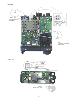
4-2 DDS ADJUSTMENT ADJUSTMENT ADJUSTMENT CONDITION DISPLAY OPERATION REFERENCE 1 • Enter the adjustment mode. FREQUENCY • Push [F1 (REF)]. 2 • Disconnect P4 from J801 (MAIN unit). • Receiving REF OSC Connect a frequency counter to P4 and set 124.032000 MHz using [DIAL]. Then push [F-4 (SET)]. After the adjustment, exit the adjustment mode and connect P4 to J801 (MAIN unit). 4-3 DISPLAY ADJUSTMENT ADJUSTMENT ADJUSTMENT CONDITION MEASUREMENT UNIT LOCATION VALUE ADJUSTMENT UNIT ADJUST DISPLAY 1 • Connect between DISPLAY unit ground and MAIN unit ground. • Disconnect J2231 (MAIN unit). • Receiving DISPLAY Connect a frequency 3.579545 MHz counter to CP536 [USA] t h r o u g h a c a p a c i t o r 4.433619 MHz (0.0047 µF) and resistor [Others] (1 kΩ) in series. DISPLAY C536 2 • Receiving Connect a frequency counter to CP505. 15.734 kHz [USA] 15.625 kHz [Others] DISPLAY R541 After the adjustment, connect J2231 (MAIN unit) and disconnect jumper wire between DISPLAY unit ground and MAIN unit ground. 4-4 TRANSMITTER ADJUSTMENT ADJUSTMENT ADJUSTMENT CONDITION DISPLAY OPERATION DRIVE/FINAL 1 • Enter the adjustment mode. IDLING • Push [F-2 (TX)]. CURRENT 2 • Connect an RF power meter to Driver Idle Cur Preset the adjustment value to "00" using [ANT1] and [ANT2] connectors. with [DIAL], and check the driving current. 3 • Apply no audio signals to [MIC] jack. • Connect a DC ammeter (5 A type) between power supply and Rotate [DIAL] to set adjustment value to 1 A value from the driving current of "00" value. Then push [F-4 (SET )]. 4 transceiver. Final Idle Cur(HF/50M)-1 Preset the adjustment value to "00" using • Transmitting with [DIAL], and check the driving current. 5 Rotate [DIAL] to set adjustment value to 1 A value from the driving current of "00" value. Then push [F-4 (SET )]. 6 Final Idle Cur(HF/50M)-2 Preset the adjustment value to "00" using with [DIAL], and check the driving current. 7 Rotate [DIAL] to set adjustment value to 1 A value from the driving current of "00" value. Then push [F-4 (SET )]. 8 Final Idle Cur(144M) Preset the adjustment value to "00" using with [DIAL], and check the driving current. 9 Rotate [DIAL] to set adjustment value to 2 A value from the driving current of "00" value. Then push [F-4 (SET )]. 10 Final Idle Cur(430M) Preset the adjustment value to "00" using with [DIAL], and check the driving current. 11 Rotate [DIAL] to set adjustment value to 2.5 A value from the driving current of "00" value. Then push [F-4 (SET )]. After the adjustment, exit the adjustment mode. 4 - 3
-
 1
1 -
2
-
3
-
4
-
5
-
6
-
7
-
8
-
9
-
10
-
11
-
12
-
 13
13 -
 14
14 -
 15
15 -
 16
16 -
 17
17 -
 18
18 -
 19
19 -
 20
20 -
 21
21 -
 22
22 -
 23
23 -
24
-
25
-
26
-
27
-
28
-
29
-
30
-
31
-
32
-
33
-
34
-
35
-
36
-
37
-
38
-
39
-
40
-
41
-
42
-
43
-
44
-
45
-
46
-
47
-
48
-
49
-
50
-
51
-
52
-
53
-
54
-
55
-
56
-
57
-
58
-
59
-
60
-
61
-
62
-
63
-
64
-
65
-
66
-
67
-
68
-
69
-
70
-
71
-
72
-
73
-
74
-
75
-
76
-
77
-
78
-
79
-
80
-
81
-
82
-
83
-
84
-
85
-
86
-
87
-
88
-
89
-
90
-
91
-
92
 |
 |
