Icom IC-7000 Service Manual - Page 9
Transmitter Circuits, 2-3 3rd Mixer Circuit Main Unit - agc
 |
View all Icom IC-7000 manuals
Add to My Manuals
Save this manual to your list of manuals |
Page 9 highlights
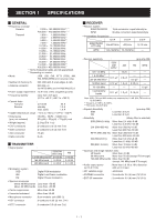
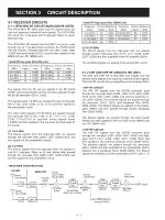
3-1-13 AGC CIRCUIT (MAIN UNIT) The AGC (Automatic Gain Control) circuit adjusts IF amplify gain to keep the audio output at a constant level. The receiver gain is determined by the voltage on the AGC line from the DSP circuit. The AGC voltage is detected at the AGC detector section inside the DSP ICs (LOGIC unit; IC301, IC2201) and the AGC voltage is applied to the D/A converter (IC2155). The converted AGC voltage is applied to the IF amplifiers (Q702, Q902, Q1001) after being amplified at IC1201 (pin 12) and sets the receiver gain with [RF/SQL] control. When receiving strong signals, the detected voltage increases and the AGC voltage decreases. As the AGC voltage is used for the bias voltage of the IF amplifiers (Q702, Q902, Q1001), IF amplifier gain is decreased. 3-1-14 S-METER CIRCUIT (LOGIC UNIT) The S-meter circuit indicates the relative received signal strength while receiving. The received signal strength is detected inside the DSP ICs (IC301, IC2201) and then applied to the main CPU (IC1302). The S-meter signal for WFM mode is output from the FM detector IC (IC401, pin 4) and then applied to the to the main CPU (IC1302, pin 123). The S-meter signal from the main CPU (IC1302) is applied to the sub CPU (DISPLAY unit; IC2003) and is then displayed on the LCD display. 3-2 TRANSMITTER CIRCUITS 3-2-1 MICROPHONE AMPLIFIER CIRCUIT (MAIN UNIT) The microphone amplifier circuit amplifies microphone audio signal to a level needed for the DSP circuit. Audio signals from the [MIC] connector (FRONT unit; J303 or MAIN unit; J2003) are amplified at the microphone amplifier (IC2007, pins 1, 2) and then applied to the DSP circuit (LOGIC unit) via J2251 (pin 3). 3-2-2 DSP CIRCUIT (LOGIC UNIT) The DSP (Digital Signal Processor) circuit enables digital PSN modulator, digital Low Power modulator, digital Phase modulator, transmitter monitor and side tone, etc. The amplified microphone signals are passed through the low-pass filter (IC502, pins 1, 2) and then applied to the A/D converter (IC551, pin 3). The converted digital audio signal are applied to the DSP ICs (IC301, IC2201) to covert into the modulated 16.15 kHz 3rd IF signal. The modulated 3rd IF signal from the DSP IC (IC301) is applied to the D/A convertor (IC551) to convert into the analog 3rd IF signal. The converted analog 3rd IF signal is output from pins 27, 28 (IC551) and then passed through the low-pass filter (IC601, pins 1-3). The filtered IF signal is applied to the 3rd mixer circuit (MAIN unit) via the J701 (pin 12). 3-2-3 3RD MIXER CIRCUIT (MAIN UNIT) The 3rd mixer circuit mixes the 3rd IF signal with the 3rd LO signal to convert into the 2nd IF frequency. 3-1-15 SQUELCH CIRCUIT (MAIN UNIT) The squelch circuit mutes audio output when the S-meter signal is lower than the [RF/SQL] control setting level. The S-meter signal from the DSP IC is applied to the main CPU (LOGIC unit; IC1302) and is compared with the threshold level set by the [RF/SQL] control. The [RF/SQL] setting is picked up at the sub CPU (DISPLAY unit; IC2003, pin 74). The main CPU (LOGIC unit; IC1302) compares the S-meter signal and [RF/SQL] setting, and outputs the mute signal via the DSP IC (IC301, pin B4) to the AF switch (IC2601, pin 2) to cut AF signals via Q2607. While receiving WFM mode, the S-meter signal is output from the WFM demodulator (IC401, pin 4) and applied to the to the main CPU (LOGIC unit; IC1302, pin 123). The main CPU (LOGIC unit; IC1302) compares the S-meter signal and [RF/SQL] setting, and outputs the mute signal via the DSP IC (IC301, pin B4) to the AF switch (IC2601, pin 2) to cut AF signals via Q2607. The filtered signal from the low-pass filter (LOGIC unit; IC601) is applied to the analog switch (IC2251, pins 1, 7) and then applied to the 3rd mixer circuit (IC1301, pins 3, 5). The applied signal is mixed with the 3rd LO signal (438.85 kHz) coming from DDS unit via J2406 (pin 13) and converted into the 455 kHz 2nd IF signal. The converted 2nd IF signal is applied to the 2nd IF circuit. 3-2-4 2ND IF CIRCUIT (MAIN UNIT) The 2nd IF circuit filters and amplifies the 2nd IF signal. The converted 2nd IF signal is applied to the 2nd IF amplifier (Q901) and then passed through the bandpass filter (FI901) via the TX switch (D903) to suppress unwanted signals. The filtered signal is applied to the 2nd mixer circuit. • AGC CIRCUIT DSPI1 IC1203 IF amp. Q1001 IF amp. 3rd mixer Q902 IF amp. Q702 IF amp. 2nd mixer Q502 IF amp. From the antenna 1st mixer DSP CIRCUIT IC301 IC2201 IC2155 IC2101 D/A converter 12 12 AGC 14 3 - 4
-
 1
1 -
2
-
3
-
 4
4 -
 5
5 -
 6
6 -
 7
7 -
 8
8 -
 9
9 -
 10
10 -
 11
11 -
 12
12 -
 13
13 -
 14
14 -
15
-
16
-
17
-
18
-
19
-
20
-
21
-
22
-
23
-
24
-
25
-
26
-
27
-
28
-
29
-
30
-
31
-
32
-
33
-
34
-
35
-
36
-
37
-
38
-
39
-
40
-
41
-
42
-
43
-
44
-
45
-
46
-
47
-
48
-
49
-
50
-
51
-
52
-
53
-
54
-
55
-
56
-
57
-
58
-
59
-
60
-
61
-
62
-
63
-
64
-
65
-
66
-
67
-
68
-
69
-
70
-
71
-
72
-
73
-
74
-
75
-
76
-
77
-
78
-
79
-
80
-
81
-
82
-
83
-
84
-
85
-
86
-
87
-
88
-
89
-
90
-
91
-
92
 |
 |
