Icom IC-7000 Service Manual - Page 17
Caution, To [dc 13.8 V] - audio adjustment
 |
View all Icom IC-7000 manuals
Add to My Manuals
Save this manual to your list of manuals |
Page 17 highlights
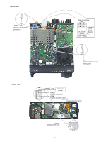
• CONNECTION • Microphone connector (Rear panel view) NOTE! Connect the test equipment to the micropho0ne connector on the rear panel, otherwise the transmitter adjustment will not adjusted properly. Pin 5 MIC GND 1 Pin 6 MIC INPUT 8 Pin 7 GND - Audio + generator + - Millivoltmerter Pin 4 PTT to [EXT SP] to [MIC] DC power supply AA13.8 V/30 A Ammeter to [DC 13.8 V] 5 A, 30 A to [ANT 1/2] AC millivoltmeter Speaker RF power meter A200 W/50 Ω Frequency counter Standard signal aagenerator CAUTION! DO NOT connect the signal generator while transmitting. 4 - 2
-
 1
1 -
2
-
3
-
4
-
5
-
6
-
7
-
8
-
9
-
10
-
11
-
 12
12 -
 13
13 -
 14
14 -
 15
15 -
 16
16 -
 17
17 -
 18
18 -
 19
19 -
 20
20 -
 21
21 -
 22
22 -
23
-
24
-
25
-
26
-
27
-
28
-
29
-
30
-
31
-
32
-
33
-
34
-
35
-
36
-
37
-
38
-
39
-
40
-
41
-
42
-
43
-
44
-
45
-
46
-
47
-
48
-
49
-
50
-
51
-
52
-
53
-
54
-
55
-
56
-
57
-
58
-
59
-
60
-
61
-
62
-
63
-
64
-
65
-
66
-
67
-
68
-
69
-
70
-
71
-
72
-
73
-
74
-
75
-
76
-
77
-
78
-
79
-
80
-
81
-
82
-
83
-
84
-
85
-
86
-
87
-
88
-
89
-
90
-
91
-
92
 |
 |

Audio
generator
RF power meter
A
200 W±50
Ω
DC power supply
AA
13.8 V±30 A
Standard signal
aa
generator
AC
millivoltmeter
CAUTION!
DO NOT
connect the
signal generator while
transmitting.
Speaker
to [EXT SP]
to [MIC]
to [DC 13.8 V]
to [ANT 1±2]
• Microphone connector
(Rear panel view)
Frequency counter
Ammeter
5 A, 30 A
Pin 5
MIC GND
Pin 6
MIC INPUT
–
+
Pin 4
PTT
Millivoltmerter
1
8
Pin 7
GND
–
+
NOTE!
Connect the test equipment to the
micropho0ne connector on the rear panel,
otherwise the transmitter adjustment will not
adjusted properly.
4 - 2
• CONNECTION