Intel BOXD955XCSLKR Product Specification
Intel BOXD955XCSLKR - Motherboard 955X Express Chipset BTX Manual
 |
UPC - 735858173834
View all Intel BOXD955XCSLKR manuals
Add to My Manuals
Save this manual to your list of manuals |
Intel BOXD955XCSLKR manual content summary:
- Intel BOXD955XCSLKR | Product Specification - Page 1
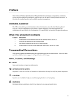
Specification July 2005 Order Number: D14066-001US The Intel® Desktop Board D955XCS may contain design defects or errors known as errata that may cause the product to deviate from published specifications. Current characterized errata are documented in the Intel Desktop Board D955XCS Specification - Intel BOXD955XCSLKR | Product Specification - Page 2
the Intel® Desktop Board D955XCS Technical Product Specification Date July 2005 This product specification applies to only the standard Intel® Desktop Board D955XCS with BIOS identifier BK95510J.86A. Changes to this specification will be published in the Intel Desktop Board D955XCS Specification - Intel BOXD955XCSLKR | Product Specification - Page 3
intended to provide detailed, technical information about the Intel Desktop Board D955XCS and its components to the vendors, system integrators, and other engineers and technicians who need this level of information. It is specifically not intended for general audiences. What This Document Contains - Intel BOXD955XCSLKR | Product Specification - Page 4
Intel Desktop Board D955XCS Technical Product Specification Other Common Notation # (NxnX) GB GB/ component, N indicates component type, xn are the relative coordinates of its location on the Desktop Board D955XCS, and X is the instance of the particular part at that general location. For example - Intel BOXD955XCSLKR | Product Specification - Page 5
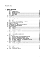
Feature Summary 10 1.1.2 Manufacturing Options 11 1.1.3 Board Layout 12 1.1.4 Block Diagram 14 1.2 Online Support ...15 1.3 Processor ...15 1.4 System Memory ...16 1.4.1 Memory Configurations 17 1.5 Intel® 955X Chipset...21 1.5.1 USB ...21 1.5.2 IDE Support 21 1.5.3 Real-Time Clock, CMOS SRAM - Intel BOXD955XCSLKR | Product Specification - Page 6
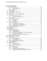
Intel Desktop Board D955XCS Technical Product Specification 2 Technical Reference Board Level 78 3 Overview of BIOS Features 3.1 Introduction ...79 3.2 Resource Configuration 80 3.2.1 PCI Autoconfiguration 80 3.2.2 PCI IDE Support 80 3.3 System Management BIOS (SMBIOS 81 3.4 Legacy USB Support - Intel BOXD955XCSLKR | Product Specification - Page 7
Contents 3.7 Fast Booting Systems with Intel® Rapid BIOS Boot 84 3.7.1 Peripheral Selection and Configuration 84 3.7.2 Intel Rapid BIOS Boot 84 3.8 BIOS Security Features 85 4 Error Messages and Beep Codes 4.1 Speaker ...87 4.2 BIOS Beep Codes...87 4.3 BIOS Error Messages 87 4.4 Port 80h - Intel BOXD955XCSLKR | Product Specification - Page 8
Intel Desktop Board D955XCS Technical Product Specification 7. Power States and Targeted System Power 38 8. Wake-up Devices and Events 39 9. System Memory Map 45 10. DMA Channels ...45 11. I/O Map ...46 12. PCI Configuration Space Map 47 13. Interrupts ...48 14. PCI Interrupt Routing Map 50 - Intel BOXD955XCSLKR | Product Specification - Page 9
1 Product Description What This Chapter Contains 1.1 Overview ...10 1.2 Online Support ...15 1.3 Processor ...15 1.4 System Memory ...16 1.5 Intel® 955X Chipset...21 1.6 Discrete Serial ATA Interface (Optional 24 1.7 PCI Express Connectors 24 1.8 Auxiliary Power (AUX PWR) Connector (Optional 25 - Intel BOXD955XCSLKR | Product Specification - Page 10
Configuration and Power Interface (ACPI), Plug and Play, SMBIOS, and Intel® Active Management Technology (Intel® AMT) • Support for PCI Local Bus Specification Revision 2.3 • Support for PCI Express* Revision 1.0a • Suspend to RAM support • Wake on PCI, RS-232, front panel, PS/2 devices, and - Intel BOXD955XCSLKR | Product Specification - Page 11
connecting an internal ATAPI CD-ROM drive to the audio mixer Audio Subsystem Intel High Definition Audio subsystem in one of the following configurations: • 8- component that enhances platform security For information about Available configurations for the board Refer to Section 1.2, page 15 11 - Intel BOXD955XCSLKR | Product Specification - Page 12
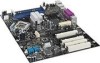
Intel Desktop Board D955XCS Technical Product Specification 1.1.3 Board Layout Figure 1 shows the location of the major components. A B F GH I J K PP C L OO D NN E MM LL KK M N O P Q JJ R II HH GG FF EE DD CC BB AA Z Y X W V U T S Figure 1. Desktop Board Components Table 3 lists - Intel BOXD955XCSLKR | Product Specification - Page 13
jumper block Z Firmware Hub (FWH) AA Auxiliary PCI Express power connector (optional) BB Speaker CC Intel 82801GR I/O Controller Hub (ICH7-R) DD LGA775 processor socket EE Intel 82955X MCH FF Battery GG Processor power connector HH Processor fan connector II DIMM Channel - Intel BOXD955XCSLKR | Product Specification - Page 14
Intel Desktop Board D955XCS Technical Product Specification 1.1.4 Block Diagram Figure 2 is a block diagram of the major functional areas of the board. PCI Express Interface PCI Express x1 Slot Secondary PCI Express x16/x4 Slot SMBus Parallel ATA IDE Connector Parallel ATA IDE Interface - Intel BOXD955XCSLKR | Product Specification - Page 15
in an LGA775 processor socket with a 1066 or 800 MHz system bus. See the Intel web site listed below for the most up-to-date list of supported processors. For information about... Supported processors for the board Refer to: http://www.intel.com/design/motherbd/cs/cs_proc.htm CAUTION Use only the - Intel BOXD955XCSLKR | Product Specification - Page 16
Intel Desktop Board D955XCS Technical Product Specification 1.4 System Memory The board has four DIMM sockets and supports the following memory features: • 1.8 V and 1.9 V DDR2 SDRAM DIMMs • Unbuffered, single-sided or double-sided DIMMs with the following restriction: Double-sided DIMMS with x16 - Intel BOXD955XCSLKR | Product Specification - Page 17
Product Description 1.4.1 Memory Configurations The Intel 82955X MCH supports two types of memory organization: • Dual channel (Interleaved) mode. This mode offers the highest throughput for real world applications. Dual channel mode is enabled when - Intel BOXD955XCSLKR | Product Specification - Page 18
Intel Desktop Board D955XCS Technical Product Specification 1.4.1.1 Dual Channel (Interleaved) Mode Configurations Figure 4 shows a dual channel configuration using two DIMMs. In this example, the DIMM0 (blue) sockets of both channels are populated - Intel BOXD955XCSLKR | Product Specification - Page 19
Product Description Figure 6 shows a dual channel configuration using four DIMMs. In this example, the combined capacity of the two DIMMs in Channel A equal the combined capacity of the two DIMMs in Channel B. Also, the DIMMs are matched between DIMM0 and DIMM1 of both channels. 256 MB 512 MB 256 - Intel BOXD955XCSLKR | Product Specification - Page 20
Intel Desktop Board D955XCS Technical Product Specification 1.4.1.2 Single Channel (Asymmetric) Mode Configurations NOTE Dual channel (Interleaved) mode configurations provide the highest memory throughput. Figure 7 shows a single channel configuration using one DIMM. In - Intel BOXD955XCSLKR | Product Specification - Page 21
the system bus, the memory bus, the PCI Express bus, and the DMI interconnect. The ICH7-R is a centralized controller for the board's I/O paths. For information about The Intel 955X chipset Resources used by the chipset Refer to http://developer.intel.com/ Chapter 2 1.5.1 USB The board supports - Intel BOXD955XCSLKR | Product Specification - Page 22
Intel Desktop Board D955XCS Technical Product Specification host to device connections, unlike Parallel ATA IDE which supports a master/slave configuration and two devices per channel. using the Windows* XP and Windows 2000 operating systems. NOTE Many Serial ATA drives use new low-voltage - Intel BOXD955XCSLKR | Product Specification - Page 23
Product Description 1.5.2.3 Serial ATA RAID The ICH7-R supports the following RAID (Redundant Array of Independent Drives) levels: • RAID 0 - data striping. Multiple physical drives can be teamed together to create one logical drive. As - Intel BOXD955XCSLKR | Product Specification - Page 24
Intel Desktop Board D955XCS Technical Product Specification 1.6 Discrete Serial ATA Interface (Optional) As a manufacturing option, the board provides a Silicon Image Sil 3114 Serial ATA (SATA) controller and four connectors (that support one device per connector) for SATA devices. These - Intel BOXD955XCSLKR | Product Specification - Page 25
Mbits/sec to 800 Mbits/sec (depending on cable type) • Connection over short and long distances • Support for both asynchronous and isochronous data transfer As a manufacturing option, the board includes three IEEE-1394a/b connectors as follows: • One IEEE-1394a connector located on the back panel - Intel BOXD955XCSLKR | Product Specification - Page 26
Intel Desktop Board D955XCS Technical Product Specification For information about The location of the (ECP) and Enhanced Parallel Port (EPP) support • Serial IRQ interface compatible with serialized IRQ support for PCI Conventional bus systems • PS/2-style mouse and keyboard interfaces • Interface - Intel BOXD955XCSLKR | Product Specification - Page 27
is connected or disconnected. For information about The location of the keyboard and mouse connectors Refer to Figure 18, page 53 1.11 Audio Subsystem The board supports the Intel High Definition audio subsystem based on the Sigmatel 9223 or the Sigmatel 9220 audio codec. The audio subsystem - Intel BOXD955XCSLKR | Product Specification - Page 28
Intel Desktop Board D955XCS Technical Product Specification 1.11.3 8-Channel (7.1) Audio Subsystem The 8-channel (7.1) audio subsystem includes the following: • Intel 82801GR I/O Controller Hub (ICH7-R) • Sigmatel 9223 audio codec • Microphone input that supports a single dynamic, condenser, or - Intel BOXD955XCSLKR | Product Specification - Page 29
Product Description Figure 10 is a block diagram of the 8-channel (7.1) audio subsystem. 82801GR I/O Controller Hub (ICH7-R) Intel High Definition Audio Link Sigmatel 9223 Audio Codec Front Panel Mic In Front Panel Line Out Mic In/Retasking Jack Side Surround L-R/Line In/Retasking - Intel BOXD955XCSLKR | Product Specification - Page 30
Intel Desktop Board D955XCS Technical Product Specification 1.11.4 6-Channel (5.1) Audio Subsystem The 6-channel (5.1) audio subsystem includes the following: • Intel 82801GR I/O Controller Hub (ICH7-R) • Sigmatel 9220 audio codec • Microphone input that supports a single dynamic, condenser, or - Intel BOXD955XCSLKR | Product Specification - Page 31
Mbits/sec) Ethernet Controller and an RJ-45 LAN connector with integrated status LEDs. 1.12.1 Intel® 82573E/82573V Gigabit Ethernet Controller The Intel 82573E/82573V Gigabit Ethernet Controller supports the following features: • PCI Express link • 10/100/1000 IEEE 802.3 compliant • Compliant to - Intel BOXD955XCSLKR | Product Specification - Page 32
Technical Product Specification 1.12.3 Alert Standard Format (ASF) Support (Optional) The board provides the following ASF support for PCI Express x1 bus add-in LAN cards and PCI Conventional bus add-in LAN cards installed in PCI Conventional bus slot 2: • Monitoring of system firmware progress - Intel BOXD955XCSLKR | Product Specification - Page 33
key features of Intel AMT include: • Secure Out of Band (OOB) system management that allows remote management of PCs regardless of system power or operating system state. ⎯ SSL3.1/TLS encryption ⎯ HTTP authentication ⎯ TCP/IP ⎯ HTTP web GUI ⎯ XML/SOAP API • Remote troubleshooting and recovery that - Intel BOXD955XCSLKR | Product Specification - Page 34
available from Intel's World Wide Web site. For information about Obtaining LAN software and drivers Refer to Section 1.2, page 15 1.13 Hardware Management Subsystem The hardware management features enable the board to be compatible with the Wired for Management (WfM) specification. The board has - Intel BOXD955XCSLKR | Product Specification - Page 35
1.13.2 Thermal Monitoring Figure 14 shows the location of the sensors and fan connectors. Product Description 1 E 3 2 1 A C 4 1 3 1 1 4 D B F G OM18045 Item A B C D E F G Description Remote ambient temperature sensor Thermal diode, located on processor die Ambient temperature sensor, - Intel BOXD955XCSLKR | Product Specification - Page 36
control over the power management and Plug and Play functions of a computer. The use of ACPI with this board requires an operating system that provides full ACPI support. ACPI features include: • Plug and Play (including bus and device enumeration) • Power management control of individual devices - Intel BOXD955XCSLKR | Product Specification - Page 37
switch is pressed for Less than four seconds Less than four seconds More than four seconds Less than four seconds More than four seconds ...the system enters this state Power-on (ACPI G0 - working state) Soft-off/Standby (ACPI G1 - sleeping state) Fail safe power-off (ACPI G2/G5 - Soft off - Intel BOXD955XCSLKR | Product Specification - Page 38
Intel Desktop Board D955XCS Technical Product Specification Table 7 lists the power states supported by the board along with the associated system power targets. See the ACPI specification for a complete description of the various system and power states. Table 7. Power States and Targeted System - Intel BOXD955XCSLKR | Product Specification - Page 39
the devices or specific events that can wake the computer from specific states. Table system that provides full ACPI support. In addition, software, drivers, and peripherals must fully support ACPI wake events. 1.14.2 Hardware Support devices supported and manufacturing options. The board provides - Intel BOXD955XCSLKR | Product Specification - Page 40
Intel Desktop Board D955XCS Technical Product Specification NOTE The use of Resume on Ring and Wake from USB technologies from an ACPI state requires an operating system that provides full ACPI support. 1.14.2.1 Power Connector When an ACPI-enabled system receives the appropriate command, the - Intel BOXD955XCSLKR | Product Specification - Page 41
the PCI Bus Power Management Interface Specification. Add-in boards that also support this specification can participate in power management and can be used to wake the computer. The use of Instantly Available PC technology requires operating system support and PCI 2.3 compliant add-in cards - Intel BOXD955XCSLKR | Product Specification - Page 42
Intel Desktop Board D955XCS Technical Product Specification 1.14.2.10 +5 V Standby Power Indicator LED The +5 V The optional Trusted Platform Module (TPM) is a component on the desktop board that is specifically designed to enhance platform security above-and-beyond the capabilities of today's - Intel BOXD955XCSLKR | Product Specification - Page 43
Considerations 71 2.12 Reliability...73 2.13 Environmental ...74 2.14 Regulatory Compliance 75 2.1 Memory Resources 2.1.1 Addressable Memory The board utilizes 8 GB of addressable system memory. Typically the address space that is allocated for PCI Conventional bus add-in cards, PCI Express - Intel BOXD955XCSLKR | Product Specification - Page 44
Intel Desktop Board D955XCS Technical Product Specification 8 GB Top of System Address Space FLASH APIC Reserved Upper DRAM Range DOS Compatibility Memory Top of usable DRAM (memory visible to the operating system) 1 MB 640 KB 0 MB 0FFFFFH 0F0000H 0EFFFFH 0E0000H 0DFFFFH 0C0000H 0BFFFFH 0A0000H - Intel BOXD955XCSLKR | Product Specification - Page 45
Technical Reference 2.1.2 Memory Map Table 9 lists the system memory map. Table 9. System Memory Map Address Range (decimal) 1024 K - 8388608 K 960 K - or 16 bits 16 bits 16 bits 16 bits System Resource Open Parallel port Diskette drive Parallel port (for ECP or EPP) DMA controller Open Open - Intel BOXD955XCSLKR | Product Specification - Page 46
Intel Desktop Board D955XCS Technical Product Specification 2.3 Fixed I/O Map Table 11. I/O Map Address (hex) 0000 - 00FF 4 bytes 1 byte 4 bytes 8 bytes 8 bytes Description Used by the Desktop Board D955XCS. Refer to the ICH7-R data sheet for dynamic addressing information. Secondary Parallel ATA - Intel BOXD955XCSLKR | Product Specification - Page 47
02 03 00 01 02 03 07 00 00 01 02 03 00 00 00 00 00 00 Description Memory controller of Intel 82955X component PCI Express x16 graphics port Intel High Definition Audio Controller PCI Express port 1 PCI Express port 2 PCI Express port 3 PCI Express port 4 USB UHCI controller 1 USB UHCI - Intel BOXD955XCSLKR | Product Specification - Page 48
Intel Desktop Board D955XCS Technical Product Specification 2.5 Interrupts The interrupts can be routed through either the Programmable Interrupt Controller (PIC) or the Advanced Programmable Interrupt Controller (APIC) portion of the ICH7-R component. The PIC is supported in Windows 98 SE and - Intel BOXD955XCSLKR | Product Specification - Page 49
and onboard PCI Conventional devices. The PCI Conventional specification describes how interrupts can be shared between devices attached signals. Some PCI Conventional interrupt sources are electrically tied together on the board and therefore share the same interrupt. Table 14 shows an example of - Intel BOXD955XCSLKR | Product Specification - Page 50
Intel Desktop Board D955XCS Technical Product Specification Table 14. PCI Interrupt Routing Map PCI Interrupt Source IEEE-1394a/b controller PCI bus connector 1 PCI bus connector 2 PCI bus connector 3 PCI bus connector 4 PIRQA - Intel BOXD955XCSLKR | Product Specification - Page 51
by the external devices could cause damage to the computer, the power cable, and the external devices themselves. This section describes the board's connectors. The connectors can be divided into these groups: • Back panel I/O connectors • Component-side I/O connectors (see page 54) 2.7.1 Back Panel - Intel BOXD955XCSLKR | Product Specification - Page 52
Intel Desktop Board D955XCS Technical Product Specification 2.7.1.1 Back Panel Connectors For 8-Channel (7.1) Audio Subsystem Figure 17 shows the location of the back panel connectors for boards equipped with the 8-channel (7.1) audio subsystem. The back panel connectors are color-coded. The figure - Intel BOXD955XCSLKR | Product Specification - Page 53
Technical Reference 2.7.1.2 Back Panel Connectors For 6-Channel (5.1) Audio Subsystem Figure 18 shows the location of the back panel connectors for boards equipped with the 6-channel (5.1) audio subsystem. The back panel connectors are color-coded. The figure legend (Table 16) lists the colors used - Intel BOXD955XCSLKR | Product Specification - Page 54
Intel Desktop Board D955XCS Technical Product Specification 2.7.2 Component-side Connectors Figure 19 shows the locations of the component-side connectors. A B CDE FGH I J K L M N O P Q 12 24 12 4 1 1 1 13 3 39 40 1 4 1 4 1 10 2 4 4 1 1 GG FF EE - Intel BOXD955XCSLKR | Product Specification - Page 55
Technical Reference Table 17. Component-side Connectors Shown in Figure 19 Item/callout from Figure 19 Description A ATAPI CD-ROM connector (optional) B Parallel ATA IDE connector C Chassis intrusion connector D Serial ATA connector 0 (ICH7-R RAID) E Serial ATA connector 1 (ICH7-R RAID) - Intel BOXD955XCSLKR | Product Specification - Page 56
Intel Desktop Board D955XCS Technical Product Specification Table 18. ATAPI CD-ROM Connector (Optional) Pin Signal Name 1 Left audio input from CD-ROM 2 CD audio differential ground 3 CD audio differential ground 4 Right - Intel BOXD955XCSLKR | Product Specification - Page 57
Technical Reference Table 22. Chassis Intrusion Connector Pin Signal Name 1 Intruder 2 Ground Table 23. Serial ATA Connectors Pin Signal Name 1 Ground 2 TXP 3 TXN 4 Ground 5 RXN 6 RXP 7 Ground Table 24. Auxiliary Power (AUX PWR) Output Connector (Optional) Pin Signal Name - Intel BOXD955XCSLKR | Product Specification - Page 58
Intel Desktop Board D955XCS Technical Product Specification 2.7.2.1 Power Supply Connectors The board has three power supply connectors: • Main power - a 2 x 12 connector. The board requires a power supply with a 2 x 12 main power cable. • Processor power - This connector provides power directly to - Intel BOXD955XCSLKR | Product Specification - Page 59
Technical Reference Table 25. Main Power Connector Pin Signal Name Pin 1 +3.3 V 13 2 +3.3 V 14 3 Ground 15 4 +5 V 16 5 Ground 17 6 +5 V 18 7 Ground 19 8 PWRGD (Power Good) 20 9 +5 V (Standby) 21 10 +12 V 22 11 +12 V 23 12 2 x 12 connector detect 24 Table 26. - Intel BOXD955XCSLKR | Product Specification - Page 60
Intel Desktop Board D955XCS Technical Product Specification 2.7.2.2 Add-in Card Connectors The board has the following add-in card connectors: • PCI Express x16; one connector supporting simultaneous transfers up to 8 GBytes/sec • Secondary PCI Express x16/x4 bus; one connector supporting - Intel BOXD955XCSLKR | Product Specification - Page 61
Technical Reference 2.7.2.4 Front Panel Connector This section describes the functions of the front panel connector. Table 30 lists the signal names of the front panel connector. Figure 20 is a connection diagram for the front panel connector. Table 30. Front Panel Connector Pin Signal In/Out - Intel BOXD955XCSLKR | Product Specification - Page 62
Intel Desktop Board D955XCS Technical Product Specification 2.7.2.4.1 Hard Drive Activity LED Connector [Yellow] Pins 1 and 31 and Table 32 are suggested colors only. Actual LED colors are product- or customer-specific. 2.7.2.4.4 Power Switch Connector [Red] Pins 6 and 8 [Red] can be connected to - Intel BOXD955XCSLKR | Product Specification - Page 63
one USB port. • Pins 2, 4, 6, and 8 comprise one USB port. • Use only a front panel USB connector that conforms to the USB 2.0 specification for high- performance USB devices. Power (+5 V DC) One D− USB Port D+ Ground Key (no pin) 1 2 3 4 5 6 7 8 10 Power (+5 V DC) D− One USB - Intel BOXD955XCSLKR | Product Specification - Page 64
Intel Desktop Board D955XCS Technical Product Specification 2.7.2.6 Front Panel IEEE 1394a/b Connectors (Optional) Figure 22 is a connection diagram for the IEEE 1394a/b connectors. TPA+ 1 2 TPA− Ground TPB+ 3 4 Ground 5 6 TPB− +12 V DC 7 8 +12 V - Intel BOXD955XCSLKR | Product Specification - Page 65
the jumper with the power on. Always turn off the power and unplug the power cord from the computer before changing a jumper setting. Otherwise, the board could be damaged. Figure 23 shows the location of the jumper block. The 3-pin jumper block determines the BIOS Setup program's mode. Table 33 - Intel BOXD955XCSLKR | Product Specification - Page 66
Intel Desktop Board D955XCS Technical Product Specification 2.9 Mechanical Considerations 2.9.1 Form Factor The board is designed to fit into a BTX-form-factor chassis. Figure 24 illustrates the mechanical form factor for the board. Dimensions are given in inches [millimeters]. The outer - Intel BOXD955XCSLKR | Product Specification - Page 67
board must meet specific dimension and material requirements. Systems based on this board need the back panel I/O shield to pass certification testing. Figure 25 shows the I/O shield for boards only. I/O shields compliant with the BTX specification are available from Intel. 1.55 REF [0.061] 172.9 - Intel BOXD955XCSLKR | Product Specification - Page 68
Intel Desktop Board D955XCS Technical Product Specification 1.55 REF [0.061] 9.65 [0.38] Ø 1.00 [0.039] A 0.00 [0.00] 9.18 [0.36] 9.40 [0.37] 172.9 REF [6.808] 13.0 354] 140.39 [5.53] Pictorial View OM17995 Figure 26. I/O Shield Dimensions for Boards with the 6-Channel (5.1) Audio Subsystem 68 - Intel BOXD955XCSLKR | Product Specification - Page 69
based on specific processor values or memory configurations but are based on the minimum and maximum current draw possible from the board's power to determine the overall system power requirements. The selection of a power supply at the system level is dependent on the system's usage model and not - Intel BOXD955XCSLKR | Product Specification - Page 70
Intel Desktop Board D955XCS Technical Product Specification 2.10.3 Fan Connector Current Capability CAUTION The total amount of standby current required depends on the wake devices supported and manufacturing options. System integrators should refer to the power usage values listed in Table 34 - Intel BOXD955XCSLKR | Product Specification - Page 71
the supported ranges, the temperature in the processor voltage regulator area will rise. This area of the board (item system design remains solely with the reader. Intel makes no warranties or representations that merely following the instructions presented in this document will result in a system - Intel BOXD955XCSLKR | Product Specification - Page 72
Intel Desktop Board D955XCS Technical Product Specification AB C Item A B C D E E D Description Intel 82955X MCH Intel 82801GR ICH7-R 1.5 V core and front side bus voltage regulator areas Processor Processor voltage regulator area OM18049 Figure 28. Localized High Temperature Zones CAUTION - Intel BOXD955XCSLKR | Product Specification - Page 73
cool the board. Table 36. Thermal Considerations for Components Component Processor voltage regulator area Temperature 120 oC (under bias) Intel Pentium 4 processor Intel 82955X MCH Intel 82801GR ICH7-R For processor case temperature, see processor datasheets and processor specification updates - Intel BOXD955XCSLKR | Product Specification - Page 74
Intel Desktop Board D955XCS Technical Product Specification 2.13 Environmental Table 37 lists the environmental specifications for the board. Table 37. Environmental Specifications Parameter Temperature Non-Operating Operating Shock Unpackaged Packaged Vibration Unpackaged Packaged Specification - Intel BOXD955XCSLKR | Product Specification - Page 75
electromagnetic compatibility (EMC) regulations. 2.14.1 Safety Regulations Table 38 lists the safety regulations the Desktop Board D955XCS complies with when correctly installed in a compatible host system. Table 38. Safety Regulations Regulation UL 60950-1:2003/ CSA C22.2 No. 60950-1-03 EN 60950 - Intel BOXD955XCSLKR | Product Specification - Page 76
Intel Desktop Board D955XCS Technical Product Specification 2.14.2.1 FCC Compliance Statement (USA) Product Type: D955XCS Desktop Board This device complies with and, if not installed and used in accordance with the instructions, may cause harmful interference to radio communications. However, there - Intel BOXD955XCSLKR | Product Specification - Page 77
tillverkats i enlighet med EG-direktiv 89/336/EEC & 73/23/EEC. 2.14.4 Recycling Considerations Intel encourages its customers to recycle its products and their components (e.g., batteries, circuit boards, plastic enclosures, etc.) whenever possible. In the U.S., a list of recyclers in your area can - Intel BOXD955XCSLKR | Product Specification - Page 78
Intel Desktop Board D955XCS Technical Product Specification 2.14.5 Product Certification Markings (Board Level) Table 40 lists the board's product certification markings. Table 40. Product Certification Markings Description UL joint US/Canada Recognized Component mark. Includes adjacent UL file - Intel BOXD955XCSLKR | Product Specification - Page 79
System Management BIOS (SMBIOS 81 3.4 Legacy USB Support...81 3.5 BIOS Updates ...82 3.6 Boot Options ...83 3.7 Fast Booting Systems with Intel configuration utility, and Plug and Play support. The BIOS displays a message during test begins and before the operating system boot begins. The menu bar is - Intel BOXD955XCSLKR | Product Specification - Page 80
Intel Desktop Board D955XCS Technical Product Specification Table and other system resources. Any interrupts set to Available in Setup are considered to be available for use by the add-in card. 3.2.2 PCI IDE Support If options by specifying manual configuration in the BIOS Setup program. 80 - Intel BOXD955XCSLKR | Product Specification - Page 81
SMBIOS information. The BIOS supports an SMBIOS table interface for such operating systems. Using this support, an SMBIOS service-level application running on a non-Plug and Play operating system can obtain the SMBIOS information. 3.4 Legacy USB Support Legacy USB support enables USB devices to be - Intel BOXD955XCSLKR | Product Specification - Page 82
Intel Desktop Board D955XCS Technical Product Specification 6. After the operating system loads the USB drivers, all legacy and non-legacy USB devices are recognized by the operating system, and Legacy USB support from the BIOS is no longer used. To install an operating system that supports USB, - Intel BOXD955XCSLKR | Product Specification - Page 83
3.6.1 CD-ROM Boot Booting from CD-ROM is supported in compliance to the El Torito bootable CD-ROM format specification. Under the Boot menu in the BIOS Setup program has been designed so that after passing the POST, the operating system loader is invoked even if the following devices are not present: - Intel BOXD955XCSLKR | Product Specification - Page 84
Intel Desktop Board D955XCS Technical Product Specification 3.7 Fast Booting Systems with Intel® Rapid BIOS Boot These factors affect the amount of time for a system to complete boot process: • Selecting and configuring peripherals properly • Using an optimized BIOS, such as the Intel® Rapid BIOS - Intel BOXD955XCSLKR | Product Specification - Page 85
Overview of BIOS Features 3.8 BIOS Security Features The BIOS includes security features that restrict access to the BIOS Setup program and who can boot the computer. A supervisor password and a user password can be set for the BIOS Setup program and for booting the computer, with the following - Intel BOXD955XCSLKR | Product Specification - Page 86
Intel Desktop Board D955XCS Technical Product Specification 86 - Intel BOXD955XCSLKR | Product Specification - Page 87
87 4.4 Port 80h POST Codes 88 4.1 Speaker The board-mounted speaker provides audible error code (beep code) information occurs during POST, the BIOS displays an error message describing the problem (see Table 45). Table 45. Beep Codes Type Memory error System did not find a device to boot. 87 - Intel BOXD955XCSLKR | Product Specification - Page 88
Intel Desktop Board D955XCS Technical Product Specification 4.4 Port 80h POST Codes During the POST, the BIOS generates diagnostic progress codes (POST-codes) to I/O port 80h. If the POST fails, execution stops and - Intel BOXD955XCSLKR | Product Specification - Page 89
Error Messages and Beep Codes Table 48. Port 80h POST Codes POST Code 10 11 12 13 21 22 23 24 25 26 27 28 50 51 52 53 - 57 58 59 5A 5B 5C 5D 70 71 72 78 79 7A Description of POST Operation Host Processor Power-on initialization of the host processor (Boot Strap Processor) Host processor Cache - Intel BOXD955XCSLKR | Product Specification - Page 90
Intel Desktop Board D955XCS Technical Product Specification Table 48. Port 80h POST Codes (continued) POST Code 90 the keyboard Detecting the presence of the keyboard Enabling the keyboard Clearing keyboard input buffer Instructing keyboard controller to run Self Test (PS2 only) Mouse (PS2 or USB) - Intel BOXD955XCSLKR | Product Specification - Page 91
OS Boot F4 Entering Sleep state F5 Exiting Sleep state F8 EFI boot service ExitBootServices ( ) has been called F9 EFI runtime service SetVirtualAddressMap ( ) has been called FA EFI runtime service ResetSystem ( ) has been called PEIMs/Recovery 30 Crisis Recovery has initiated per User - Intel BOXD955XCSLKR | Product Specification - Page 92
Intel Desktop Board D955XCS Technical Product Specification Table 49. Typical Port 80h POST Sequence POST Code 21 22 23 25 28 34 E4 12 13 50 51 92 90 94 95 EB
-
 1
1 -
 2
2 -
 3
3 -
 4
4 -
 5
5 -
 6
6 -
 7
7 -
8
-
9
-
10
-
11
-
12
-
13
-
14
-
15
-
16
-
17
-
18
-
19
-
20
-
21
-
22
-
23
-
24
-
25
-
26
-
27
-
28
-
29
-
30
-
31
-
32
-
33
-
34
-
35
-
36
-
37
-
38
-
39
-
40
-
41
-
42
-
43
-
44
-
45
-
46
-
47
-
48
-
49
-
50
-
51
-
52
-
53
-
54
-
55
-
56
-
57
-
58
-
59
-
60
-
61
-
62
-
63
-
64
-
65
-
66
-
67
-
68
-
69
-
70
-
71
-
72
-
73
-
74
-
75
-
76
-
77
-
78
-
79
-
80
-
81
-
82
-
83
-
84
-
85
-
86
-
87
-
88
-
89
-
90
-
91
-
92
 |
 |

July 2005
Order Number:
D14066-001US
The Intel
®
Desktop Board D955XCS may contain design defects or errors known as errata that may cause the product to deviate from published specifications.
Current
characterized errata are documented in the Intel Desktop Board D955XCS Specification Update.
Intel
®
Desktop Board
D955XCS
Technical Product Specification