Intel BOXD955XCSLKR Product Specification - Page 24
Discrete Serial ATA Interface Optional, 7 PCI Express, Connectors
 |
UPC - 735858173834
View all Intel BOXD955XCSLKR manuals
Add to My Manuals
Save this manual to your list of manuals |
Page 24 highlights
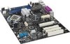
Intel Desktop Board D955XCS Technical Product Specification 1.6 Discrete Serial ATA Interface (Optional) As a manufacturing option, the board provides a Silicon Image Sil 3114 Serial ATA (SATA) controller and four connectors (that support one device per connector) for SATA devices. These connectors are in addition to the four SATA connectors of the ICH7-R SATA interface. The Sil 3114 controller uses the PCI bus for data transfer and provides a maximum data transfer rate of up to 1.5 Gbits/sec. The discrete SATA interface supports the following RAID levels: • RAID 0 • RAID 1 • RAID 0+1 For information about RAID levels The location of the discrete SATA RAID connectors Refer to Section 1.5.2.3, page 23 Figure 19, page 54 1.7 PCI Express* Connectors The board provides the following PCI Express connectors: • One PCI Express x16 connector. The x16 interface supports simultaneous (full duplex) transfers up to 8 GBytes/sec. Single-ended (half duplex) transfers are supported at up to 4 GBytes/sec. • One Secondary PCI Express x16/x4 bus add-in card connector: The board provides a PCI Express add-in card connector in the form of a physical x16 connector with electrical routing of x4. It is important to note that this connector is an electrical equivalent of a PCI Express x4 bus add-in card connector. This connector supports x4 and x1 PCI Express add-in cards. • One PCI Express x1 connector. The x1 interface supports simultaneous transfers up to 500 MBytes/sec. # INTEGRATOR'S NOTE Although the PCI Express specification allows x16 cards to auto-negotiate down from x16 to x4 and x1 and may function properly, such configurations have not been validated on this board. Please consult your add-in card vendor prior to attempting to use a PCI Express x16 add-in card in this connector. The PCI Express interface supports the PCI Conventional bus configuration mechanism so that the underlying PCI Express architecture is compatible with PCI Conventional compliant operating systems. Additional features of the PCI Express interface includes the following: • Support for the PCI Express enhanced configuration mechanism • Automatic discovery, link training, and initialization • Support for Active State Power Management (ASPM) • SMBus 2.0 support • Wake# signal supporting wake events from ACPI S1, S3, S4, or S5 • Software compatible with the PCI Power Management Event (PME) mechanism defined in the PCI Power Management Specification Rev. 1.1 24
-
 1
1 -
2
-
3
-
4
-
5
-
6
-
7
-
8
-
9
-
10
-
11
-
12
-
13
-
14
-
15
-
16
-
17
-
18
-
 19
19 -
 20
20 -
 21
21 -
 22
22 -
 23
23 -
 24
24 -
 25
25 -
 26
26 -
 27
27 -
 28
28 -
 29
29 -
30
-
31
-
32
-
33
-
34
-
35
-
36
-
37
-
38
-
39
-
40
-
41
-
42
-
43
-
44
-
45
-
46
-
47
-
48
-
49
-
50
-
51
-
52
-
53
-
54
-
55
-
56
-
57
-
58
-
59
-
60
-
61
-
62
-
63
-
64
-
65
-
66
-
67
-
68
-
69
-
70
-
71
-
72
-
73
-
74
-
75
-
76
-
77
-
78
-
79
-
80
-
81
-
82
-
83
-
84
-
85
-
86
-
87
-
88
-
89
-
90
-
91
-
92
 |
 |
