Intel D845GLAD Product Guide - Page 23
Connecting the Processor Fan Heat Sink Cable, Removing a Processor, Installing and Removing Memory - specification
 |
UPC - 735858153386
View all Intel D845GLAD manuals
Add to My Manuals
Save this manual to your list of manuals |
Page 23 highlights
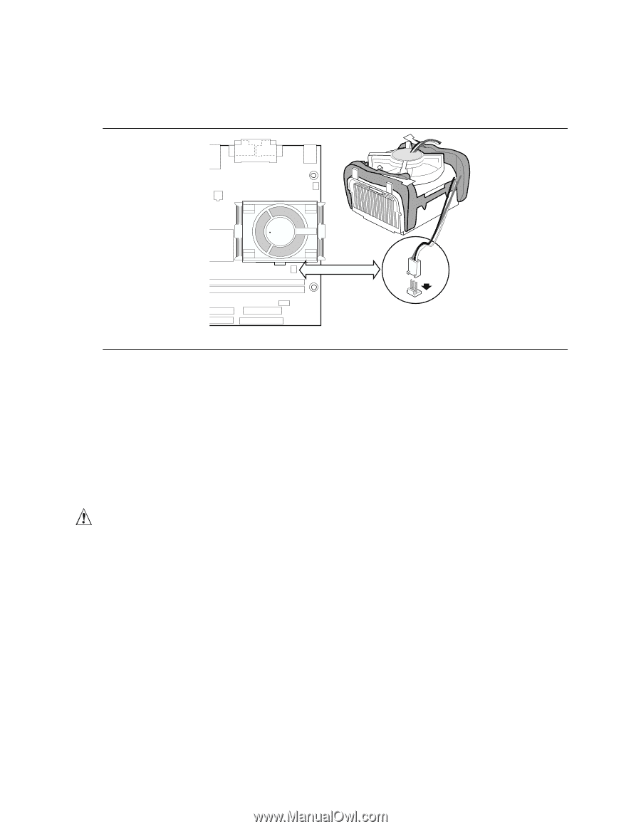
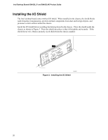
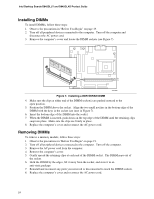
Installing and Replacing Desktop Board Components Connecting the Processor Fan Heat Sink Cable Connect the processor fan heat sink cable to the processor fan connector (see Figure 6). OM13684 Figure 6. Connecting the Processor Fan Heat Sink Cable to the Processor Fan Connector Removing a Processor For instruction on how to remove the processor fan heat sink, refer to the processor installation manual or the Intel World Wide Web site at: http://support.intel.com/support/processors/pentium4/intnotes478.htm Installing and Removing Memory CAUTION To be fully compliant with all applicable Intel SDRAM memory specifications, the boards require DIMMs that support the Serial Presence Detect (SPD) data structure. You can access the PC Serial Presence Detect Specification at: http://www.intel.com/technology/memory/pcsdram/spec/ ✏ NOTE Remove the PCI bus connector 1 card before installing or upgrading memory to avoid interference with the memory retention mechanism. Desktop Boards D845GLLY and D845GLAD have two DIMM sockets arranged as banks 0 and 1, as shown in Figure 7. If installing a single DIMM, install it in bank 0. Refer to the Main Memory heading on page 11 for memory requirements. 23
-
 1
1 -
2
-
3
-
4
-
5
-
6
-
7
-
8
-
9
-
10
-
11
-
12
-
13
-
14
-
15
-
16
-
17
-
 18
18 -
 19
19 -
 20
20 -
 21
21 -
 22
22 -
 23
23 -
 24
24 -
 25
25 -
 26
26 -
 27
27 -
 28
28 -
29
-
30
-
31
-
32
-
33
-
34
-
35
-
36
-
37
-
38
-
39
-
40
-
41
-
42
-
43
-
44
-
45
-
46
-
47
-
48
-
49
-
50
-
51
-
52
-
53
-
54
-
55
-
56
-
57
-
58
-
59
-
60
-
61
-
62
-
63
-
64
-
65
-
66
-
67
-
68
-
69
-
70
-
71
-
72
-
73
-
74
-
75
-
76
 |
 |