Intel D915GAG Product Specification - Page 106
Speaker, BIOS Beep Codes
 |
View all Intel D915GAG manuals
Add to My Manuals
Save this manual to your list of manuals |
Page 106 highlights
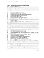
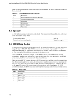
Intel Desktop Board D915GAV/D915GAG Technical Product Specification Table 56 describes the lower nibble of the high byte and indicates the bus on which the routines are being executed. Table 56. Lower Nibble High Byte Functions Value 0 1 2 3 4 5 Description Generic DIM (Device Initialization Manager) On-board System devices ISA devices EISA devices ISA PnP devices PCI devices 4.4 Speaker A 47 Ω inductive speaker is mounted on the board. The speaker provides audible error code (beep code) information during POST. For information about The location of the onboard speaker Refer to Figure 1, on page 14 4.5 BIOS Beep Codes Whenever a recoverable error occurs during POST, the BIOS displays an error message describing the problem (see Table 57). The BIOS also issues a beep code (one long tone followed by two short tones) during POST if the video configuration fails (a faulty video card or no card installed) or if an external ROM module does not properly checksum to zero. An external ROM module (for example, a video BIOS) can also issue audible errors, usually consisting of one long tone followed by a series of short tones. For more information on the beep codes issued, check the documentation for that external device. There are several POST routines that issue a POST terminal error and shut down the system if they fail. Before shutting down the system, the terminal-error handler issues a beep code signifying the test point error, writes the error to I/O port 80h, attempts to initialize the video and writes the error in the upper left corner of the screen (using both monochrome and color adapters). If POST completes normally, the BIOS issues one short beep before passing control to the operating system. Table 57. Beep Codes Beep 1 3 6 7 8 Description CPU error Memory error System failure System failure Video error 106
-
 1
1 -
2
-
3
-
4
-
5
-
6
-
7
-
8
-
9
-
10
-
11
-
12
-
13
-
14
-
15
-
16
-
17
-
18
-
19
-
20
-
21
-
22
-
23
-
24
-
25
-
26
-
27
-
28
-
29
-
30
-
31
-
32
-
33
-
34
-
35
-
36
-
37
-
38
-
39
-
40
-
41
-
42
-
43
-
44
-
45
-
46
-
47
-
48
-
49
-
50
-
51
-
52
-
53
-
54
-
55
-
56
-
57
-
58
-
59
-
60
-
61
-
62
-
63
-
64
-
65
-
66
-
67
-
68
-
69
-
70
-
71
-
72
-
73
-
74
-
75
-
76
-
77
-
78
-
79
-
80
-
81
-
82
-
83
-
84
-
85
-
86
-
87
-
88
-
89
-
90
-
91
-
92
-
93
-
94
-
95
-
96
-
97
-
98
-
99
-
100
-
 101
101 -
 102
102 -
 103
103 -
 104
104 -
 105
105 -
 106
106
 |
 |
