Intel D915GAG Product Specification - Page 43
Table 11., Power States and Targeted System Power
 |
View all Intel D915GAG manuals
Add to My Manuals
Save this manual to your list of manuals |
Page 43 highlights
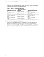
Product Description Table 11 lists the power states supported by the boards along with the associated system power targets. See the ACPI specification for a complete description of the various system and power states. Table 11. Power States and Targeted System Power Global States G0 - working state Sleeping States S0 - working Processor States C0 - working Device States D0 - working state. Targeted System Power (Note 1) Full power > 30 W G1 - sleeping state S1 - Processor stopped C1 - stop grant G1 - sleeping state G1 - sleeping state G2/S5 G3 - mechanical off AC power is disconnected from the computer. S3 - Suspend to RAM. Context saved to RAM. S4 - Suspend to disk. Context saved to disk. S5 - Soft off. Context not saved. Cold boot is required. No power to the system. No power No power No power No power D1, D2, D3 - device specification specific. D3 - no power except for wake-up logic. D3 - no power except for wake-up logic. D3 - no power except for wake-up logic. 5 W < power < 52.5 W Power < 5 W (Note 2) Power < 5 W (Note 2) Power < 5 W (Note 2) D3 - no power for wake-up logic, except when provided by battery or external source. No power to the system. Service can be performed safely. Notes: 1. Total system power is dependent on the system configuration, including add-in boards and peripherals powered by the system chassis' power supply. 2. Dependent on the standby power consumption of wake-up devices used in the system. 43
-
 1
1 -
2
-
3
-
4
-
5
-
6
-
7
-
8
-
9
-
10
-
11
-
12
-
13
-
14
-
15
-
16
-
17
-
18
-
19
-
20
-
21
-
22
-
23
-
24
-
25
-
26
-
27
-
28
-
29
-
30
-
31
-
32
-
33
-
34
-
35
-
36
-
37
-
 38
38 -
 39
39 -
 40
40 -
 41
41 -
 42
42 -
 43
43 -
 44
44 -
 45
45 -
 46
46 -
 47
47 -
 48
48 -
49
-
50
-
51
-
52
-
53
-
54
-
55
-
56
-
57
-
58
-
59
-
60
-
61
-
62
-
63
-
64
-
65
-
66
-
67
-
68
-
69
-
70
-
71
-
72
-
73
-
74
-
75
-
76
-
77
-
78
-
79
-
80
-
81
-
82
-
83
-
84
-
85
-
86
-
87
-
88
-
89
-
90
-
91
-
92
-
93
-
94
-
95
-
96
-
97
-
98
-
99
-
100
-
101
-
102
-
103
-
104
-
105
-
106
 |
 |
