Intel D915GAG Product Specification - Page 29
Serial ATA Interfaces - windows 7
 |
View all Intel D915GAG manuals
Add to My Manuals
Save this manual to your list of manuals |
Page 29 highlights
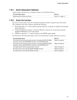
Product Description NOTE ATA-66 and ATA-100 are faster timings and require a specialized cable to reduce reflections, noise, and inductive coupling. The Parallel ATA IDE interface also supports ATAPI devices (such as CD-ROM drives) and ATA devices using the transfer modes. The BIOS supports Logical Block Addressing (LBA) and Extended Cylinder Head Sector (ECHS) translation modes. The drive reports the transfer rate and translation mode to the BIOS. The boards support Laser Servo (LS-120) diskette technology through the Parallel ATA IDE interfaces. An LS-120 drive can be configured as a boot device by setting the BIOS Setup program's Boot menu to one of the following: • ARMD-FDD (ATAPI removable media device - floppy disk drive) • ARMD-HDD (ATAPI removable media device - hard disk drive) For information about The location of the Parallel ATA IDE connector on the D915GAV board The location of the Parallel ATA IDE connector on the D915GAG board Refer to Figure 19, page 66 Figure 20, page 68 1.7.3.2 Serial ATA Interfaces The ICH6's Serial ATA controller offers four independent Serial ATA ports with a theoretical maximum transfer rate of 150 MB/s per port. One device can be installed on each port for a maximum of four Serial ATA devices. A point-to-point interface is used for host to device connections, unlike Parallel ATA IDE which supports a master/slave configuration and two devices per channel. For compatibility, the underlying Serial ATA functionality is transparent to the operating system. The Serial ATA controller can operate in both legacy and native modes. In legacy mode, standard IDE I/O and IRQ resources are assigned (IRQ 14 and 15). In Native mode, standard PCI Conventional bus resource steering is used. Native mode is the preferred mode for configurations using the Windows* XP and Windows 2000 operating systems. NOTE Many Serial ATA drives use new low-voltage power connectors and require adaptors or power supplies equipped with low-voltage power connectors. For more information, see: http://www.serialata.org/ For information about The location of the Serial ATA IDE connectors on the D915GAV board The location of the Serial ATA IDE connectors on the D915GAG board Refer to Figure 19, page 66 Figure 20, page 68 29
-
 1
1 -
2
-
3
-
4
-
5
-
6
-
7
-
8
-
9
-
10
-
11
-
12
-
13
-
14
-
15
-
16
-
17
-
18
-
19
-
20
-
21
-
22
-
23
-
 24
24 -
 25
25 -
 26
26 -
 27
27 -
 28
28 -
 29
29 -
 30
30 -
 31
31 -
 32
32 -
 33
33 -
 34
34 -
35
-
36
-
37
-
38
-
39
-
40
-
41
-
42
-
43
-
44
-
45
-
46
-
47
-
48
-
49
-
50
-
51
-
52
-
53
-
54
-
55
-
56
-
57
-
58
-
59
-
60
-
61
-
62
-
63
-
64
-
65
-
66
-
67
-
68
-
69
-
70
-
71
-
72
-
73
-
74
-
75
-
76
-
77
-
78
-
79
-
80
-
81
-
82
-
83
-
84
-
85
-
86
-
87
-
88
-
89
-
90
-
91
-
92
-
93
-
94
-
95
-
96
-
97
-
98
-
99
-
100
-
101
-
102
-
103
-
104
-
105
-
106
 |
 |
