Intel D925XECV2 Product Specification - Page 7

Overview of BIOS Features, Error Messages and Beep Codes, s - bios update

Page 7 highlights

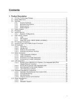
Contents 3 Overview of BIOS Features 3.1 Introduction ...95 3.2 BIOS Flash Memory Organization 96 3.3 Resource Configuration 96 3.3.1 PCI Autoconfiguration 96 3.3.2 PCI IDE Support 96 3.4 System Management BIOS (SMBIOS 97 3.5 Legacy USB Support...97 3.6 BIOS Updates ...98 3.6.1 Language Support 98 3.6.2 Custom Splash Screen 98 3.7 Boot Options ...99 3.7.1 CD-ROM Boot 99 3.7.2 Network Boot 99 3.7.3 Booting Without Attached Devices 99 3.7.4 Changing the Default Boot Device During POST 99 3.8 Fast Booting Systems with Intel® Rapid BIOS Boot 100 3.8.1 Peripheral Selection and Configuration 100 3.8.2 Intel Rapid BIOS Boot 100 3.9 BIOS Security Features 101 4 Error Messages and Beep Codes 4.1 BIOS Error Messages 103 4.2 Port 80h POST Codes 105 4.3 Bus Initialization Checkpoints 109 4.4 Speaker ...110 4.5 BIOS Beep Codes...110 Figures 1. Desktop Board D925XECV2 Components 14 2. Desktop Board D925XEBC2 Components 16 3. Block Diagram...18 4. Memory Channel and DIMM Configuration 21 5. Dual Channel (Interleaved) Mode Configuration with Two DIMMs 22 6. Dual Channel (Interleaved) Mode Configuration with Three DIMMs 22 7. Dual Channel (Interleaved) Mode Configuration with Four DIMMs 23 8. Single Channel (Asymmetric) Mode Configuration with One DIMM 24 9. Single Channel (Asymmetric) Mode Configuration with Three DIMMs 24 10. Front/Back Panel Audio Connector Options for 8-Channel (7.1) Audio Subsystem .... 32 11. 8-channel (7.1) Audio Subsystem Block Diagram 33 12. Front/Back Panel Audio Connector Options for 6-Channel (5.1) Audio Subsystem .... 34 13. 6-Channel (5.1) Audio Subsystem Block Diagram 34 14. LAN Connector LED Locations 35 15. Thermal Monitoring for D925XECV2 Board 38 16. Thermal Monitoring for D925XEBC2 Board 39 17. Location of the Standby Power Indicator LED on the D925XECV2 Board 46 18. Detailed System Memory Address Map 56 19. Back Panel Connectors for 8-Channel (7.1) Audio Subsystem 64 vii

  • 1
  • 2
  • 3
  • 4
  • 5
  • 6
  • 7
  • 8
  • 9
  • 10
  • 11
  • 12
  • 13
  • 14
  • 15
  • 16
  • 17
  • 18
  • 19
  • 20
  • 21
  • 22
  • 23
  • 24
  • 25
  • 26
  • 27
  • 28
  • 29
  • 30
  • 31
  • 32
  • 33
  • 34
  • 35
  • 36
  • 37
  • 38
  • 39
  • 40
  • 41
  • 42
  • 43
  • 44
  • 45
  • 46
  • 47
  • 48
  • 49
  • 50
  • 51
  • 52
  • 53
  • 54
  • 55
  • 56
  • 57
  • 58
  • 59
  • 60
  • 61
  • 62
  • 63
  • 64
  • 65
  • 66
  • 67
  • 68
  • 69
  • 70
  • 71
  • 72
  • 73
  • 74
  • 75
  • 76
  • 77
  • 78
  • 79
  • 80
  • 81
  • 82
  • 83
  • 84
  • 85
  • 86
  • 87
  • 88
  • 89
  • 90
  • 91
  • 92
  • 93
  • 94
  • 95
  • 96
  • 97
  • 98
  • 99
  • 100
  • 101
  • 102
  • 103
  • 104
  • 105
  • 106
  • 107
  • 108
  • 109
  • 110

Contents
vii
3
Overview of BIOS Features
3.1
Introduction
..................................................................................................................
95
3.2
BIOS Flash Memory Organization
...............................................................................
96
3.3
Resource Configuration
...............................................................................................
96
3.3.1
PCI Autoconfiguration
....................................................................................
96
3.3.2
PCI IDE Support
............................................................................................
96
3.4
System Management BIOS (SMBIOS)
........................................................................
97
3.5
Legacy USB Support
....................................................................................................
97
3.6
BIOS Updates
..............................................................................................................
98
3.6.1
Language Support
.........................................................................................
98
3.6.2
Custom Splash Screen
..................................................................................
98
3.7
Boot Options
................................................................................................................
99
3.7.1
CD-ROM Boot
...............................................................................................
99
3.7.2
Network Boot
.................................................................................................
99
3.7.3
Booting Without Attached Devices
................................................................
99
3.7.4
Changing the Default Boot Device During POST
..........................................
99
3.8
Fast Booting Systems with Intel
®
Rapid BIOS Boot
...................................................
100
3.8.1
Peripheral Selection and Configuration
.......................................................
100
3.8.2
Intel Rapid BIOS Boot
.................................................................................
100
3.9
BIOS Security Features
.............................................................................................
101
4
Error Messages and Beep Codes
4.1
BIOS Error Messages
................................................................................................
103
4.2
Port 80h POST Codes
...............................................................................................
105
4.3
Bus Initialization Checkpoints
....................................................................................
109
4.4
Speaker
.....................................................................................................................
110
4.5
BIOS Beep Codes
......................................................................................................
110
Figures
1.
Desktop Board D925XECV2 Components
...................................................................
14
2.
Desktop Board D925XEBC2 Components
...................................................................
16
3.
Block Diagram
..............................................................................................................
18
4.
Memory Channel and DIMM Configuration
..................................................................
21
5.
Dual Channel (Interleaved) Mode Configuration with Two DIMMs
..............................
22
6.
Dual Channel (Interleaved) Mode Configuration with Three DIMMs
............................
22
7.
Dual Channel (Interleaved) Mode Configuration with Four DIMMs
..............................
23
8.
Single Channel (Asymmetric) Mode Configuration with One DIMM
.............................
24
9.
Single Channel (Asymmetric) Mode Configuration with Three DIMMs
........................
24
10.
Front/Back Panel Audio Connector Options for 8-Channel (7.1) Audio Subsystem
....
32
11.
8-channel (7.1) Audio Subsystem Block Diagram
........................................................
33
12.
Front/Back Panel Audio Connector Options for 6-Channel (5.1) Audio Subsystem
....
34
13.
6-Channel (5.1) Audio Subsystem Block Diagram
.......................................................
34
14.
LAN Connector LED Locations
....................................................................................
35
15.
Thermal Monitoring for D925XECV2 Board
.................................................................
38
16.
Thermal Monitoring for D925XEBC2 Board
.................................................................
39
17.
Location of the Standby Power Indicator LED on the D925XECV2 Board
..................
46
18.
Detailed System Memory Address Map
.......................................................................
56
19.
Back Panel Connectors for 8-Channel (7.1) Audio Subsystem
...................................
64