Intel MFS5000SI User Guide
Intel MFS5000SI - Multi-Flex Server Compute Module Manual
 |
UPC - 735858196932
View all Intel MFS5000SI manuals
Add to My Manuals
Save this manual to your list of manuals |
Intel MFS5000SI manual content summary:
- Intel MFS5000SI | User Guide - Page 1
Intel® Compute Module MFS5000SI User Guide A Guide for Technically Qualified Assemblers of Intel® Identified Subassemblies/ Products Intel Order Number D90834-005 - Intel MFS5000SI | User Guide - Page 2
or death may occur. Intel may make changes to specifications and product descriptions at any time, without notice. Intel® server boards contain a number of high-density VLSI and power delivery components that need adequate airflow for cooling. Intel's own chassis are designed and tested to meet the - Intel MFS5000SI | User Guide - Page 3
declaraciones de seguridad y precaución de este documento antes de realizar cualquiera de las instrucciones. Vea Intel® Server Boards and Server Chassis Safety Information en http://support.intel.com/support/motherboards/server/sb/cs-010770.htm. Intel® Compute Module MFS5000SI User Guide iii - Intel MFS5000SI | User Guide - Page 4
enclosure cover: To protect internal components and for proper cooling and airflow, the compute module should not be inserted into the chassis with the cover removed; operating it without the enclosure cover in place can damage system parts. iv Intel® Compute Module MFS5000SI User Guide - Intel MFS5000SI | User Guide - Page 5
Processor ...5 Memory ...5 Power Supply ...6 Hardware Installations and Upgrades 7 Before You Begin ...7 Tools and Supplies Needed ...7 Installation Guidelines ...7 Removing and Installing an Intel® Compute Module MFS5000SI 7 Removing a Compute Module from the Server System 7 Installing a Compute - Intel MFS5000SI | User Guide - Page 6
...61 Server Safety Information ...61 Safety Warnings and Cautions 61 Intended Application Uses ...62 Site Selection ...62 Equipment Handling Practices 62 Power and Electrical Warnings 62 System Access Warnings ...63 Rack Mount Warnings ...64 vi Intel® Compute Module MFS5000SI User Guide - Intel MFS5000SI | User Guide - Page 7
Hazards ...65 Deutsch...66 Sicherheitshinweise für den Server 66 Sicherheitshinweise und Vorsichtsmaßnahmen 66 Zielbenutzer der E Installation/Assembly Safety Instructions 89 English ...89 Deutsch ...91 Français ...94 Español ...96 Italiano ...98 Intel® Compute Module MFS5000SI User Guide vii - Intel MFS5000SI | User Guide - Page 8
viii Intel® Compute Module MFS5000SI User Guide - Intel MFS5000SI | User Guide - Page 9
List of Tables Table 1. Compute Module Features 2 Table 2. Diagnostic LED Information 46 Table 3. POST Error Beep Codes 47 Intel® Compute Module MFS5000SI User Guide ix - Intel MFS5000SI | User Guide - Page 10
x Intel® Compute Module MFS5000SI User Guide - Intel MFS5000SI | User Guide - Page 11
Intel® Compute Module MFS5000SI 1 Figure 2. Server Board ...1 Figure 3. Component and Connector Locations 3 Figure 4. Configuration Jumper Locations 4 Figure 5. Front Panel Connectors and Indicators 5 Figure 6. Removing Top Cover 9 Figure 7. Installing Top Cover 10 Figure 8. Removing Processor - Intel MFS5000SI | User Guide - Page 12
xii Intel® Compute Module MFS5000SI User Guide - Intel MFS5000SI | User Guide - Page 13
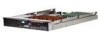
well as provides illustrations showing the location of important components and connections on the compute module. The Intel® Compute Module MFS5000SI is shown in the following pictures. Figure 1. Intel® Compute Module MFS5000SI Figure 2. Server Board Intel® Compute Module MFS5000SI User Guide 1 - Intel MFS5000SI | User Guide - Page 14
table summarizes the major features of the server board. Table 1. Compute Module Features Feature Processors Memory Chipset Peripheral Interfaces Video Hard Drive LAN Trusted Computing Description Support for up to two Dual-Core Intel® Xeon® processors 5000 sequence Support for up to 32 GB of - Intel MFS5000SI | User Guide - Page 15
(manufacturing only) O CPU #2 Heatsink P Intel® 6321ESB I/O Controller Hub Q Intel® 5000P Memory Controller Hub (MCH) R Test Connector (manufacturing only) S Serial Debug Connector (manufacturing only) Figure 3. Component and Connector Locations Intel® Compute Module MFS5000SI User Guide 3 - Intel MFS5000SI | User Guide - Page 16
Bank Select 32 Default BOOT FROM EMERGENCY BIOS IMAGE J3A3 PASSWORD CLR Default 2 CLEAR 3 PASSWORD J4A1 BMC Force Update 23 Enabled Default Disabled J7A1 CMOS CLR 32 CLEAR immediately. These pins should not be jumpered for normal operation. 4 Intel® Compute Module MFS5000SI User Guide - Intel MFS5000SI | User Guide - Page 17
Intel® Compute Module MFS5000SI supports up to two Multi-Core Intel® Xeon® Processors 5xxx Series. Memory A minimum of two fully-buffered DDR2 667 MHz DIMM(s) (FB-DIMM) should be installed. Additional DIMMs must be installed in pairs, up to eight total. Intel® Compute Module MFS5000SI User Guide - Intel MFS5000SI | User Guide - Page 18
slot) plus all other modules in the system. Three power supplies will support 4 to 6 compute modules (in any slot) plus all other modules in the system. Any additional power supplies above minimum required (based on configuration) provides redundancy. 6 Intel® Compute Module MFS5000SI User Guide - Intel MFS5000SI | User Guide - Page 19
Module MFS5000SI Removing a Compute Module from the Server System 1. Observe the safety and ESD information at the beginning of this manual and in the appendices. 2. If the compute module is operating, shut down the operating system and power it down. Intel® Compute Module MFS5000SI User Guide - Intel MFS5000SI | User Guide - Page 20
2. If the compute module is installed in a server system, see "Removing a Compute Module from the Server System" on page 7 for removal instructions. 3. Carefully lay the compute module down on a flat, non-conductive surface, with the cover side up. 8 Intel® Compute Module MFS5000SI User Guide - Intel MFS5000SI | User Guide - Page 21
the compute module bezel (see letter "B"). Lift the top cover up and off the compute module. Caution: Always replace the top cover before installing the compute module into a server system. B A 1 I/O 2 1 2 ID Figure 6. Removing Top Cover AF002402 Intel® Compute Module MFS5000SI User Guide 9 - Intel MFS5000SI | User Guide - Page 22
are installed and seated correctly and that no loose tools or parts are inside the compute module. Slide the top cover forward to the closed position until the retention latch fully engages. 1 I/O 2 1 2 ID Figure 7. Installing Top Cover AF002403 10 Intel® Compute Module MFS5000SI User Guide - Intel MFS5000SI | User Guide - Page 23
Module from the Server System" on page 7 for removal instructions. 3. Remove the top cover. For instructions, see "Opening and Removing the Top Cover" on page 8. 4. Remove the processor air duct. 1 I/O 2 1 2 ID Figure 8. Removing Processor Air Duct Intel® Compute Module MFS5000SI User Guide - Intel MFS5000SI | User Guide - Page 24
away from the socket to release it. Fully raise the socket handle. TP02074 Figure 9. Lifting Processor Socket Handle 6. Push the rear tab of the load plate with your finger tip (see letter easily damaged. A B Figure 10. Opening Load Plate TP02075 12 Intel® Compute Module MFS5000SI User Guide - Intel MFS5000SI | User Guide - Page 25
the processor has components that may damage the socket pins if installed improperly. Processor must align correctly with socket opening before installation. DO NOT DROP processor into socket. A B AF002223 Figure 12. Orienting and Installing Processor Intel® Compute Module MFS5000SI User Guide - Intel MFS5000SI | User Guide - Page 26
the thermal material is intact on the bottom of the heatsink. 12. Align the heatsink over the processor, thermal material side down, with the captive screws in line with the holes on the heatsink retention module. Press down firmly on the heatsink. 14 Intel® Compute Module MFS5000SI User Guide - Intel MFS5000SI | User Guide - Page 27
in a diagonal manner (see tightening order in the following figure). Do not over-tighten the screws by using excessive force. 3 2 1 4 TP02328 Figure 15. Installing Heatsink Intel® Compute Module MFS5000SI User Guide 15 - Intel MFS5000SI | User Guide - Page 28
must remain in place to ensure proper cooling. Remove the second processor air baffle by rocking the air baffle back and forth until it breaks off (see letter "A" in the following figure). A AF002410 Figure 16. Removing Second Processor Air Baffle 16 Intel® Compute Module MFS5000SI User Guide - Intel MFS5000SI | User Guide - Page 29
Duct 16. Reinstall the top cover. For instructions, see "Replacing and Closing the Top Cover" on page 10. 17. Reinstall the server compute blade in the server system. For instructions, see "Installing a Compute Module into the Server System" on page 8. Intel® Compute Module MFS5000SI User Guide 17 - Intel MFS5000SI | User Guide - Page 30
the Server System" on page 7 for removal instructions. 3. Remove the top cover. For instructions, see "Opening and Removing the Top Cover" on page 8. 4. Remove the processor air duct. 1 I/O 2 1 2 ID Figure 18. Removing Processor Air Duct AF002404 18 Intel® Compute Module MFS5000SI User Guide - Intel MFS5000SI | User Guide - Page 31
gently lifting the heatsink off the processor. 3 2 1 4 AF002221 Figure 19. Removing the Heatsink 6. Push the lever handle down and away from the socket to release it. Fully raise the socket handle. TP02074 Figure 20. Lifting Processor Socket Handle Intel® Compute Module MFS5000SI User Guide 19 - Intel MFS5000SI | User Guide - Page 32
the load plate up slightly. Open the load plate (see letter "B"). A B TP02075 Figure 21. Opening Load Plate 8. Remove processor. Note: Do not touch the socket pins; they are very sensitive and easily damaged. AF002225 Figure 22. Removing Processor 20 Intel® Compute Module MFS5000SI User Guide - Intel MFS5000SI | User Guide - Page 33
processor load plate (see letter "A" in the following figure). With your finger, push down on the load plate (see letter "B"). Lower the socket lever until it is fully latched (see letter "C"). C A B AF002224 Figure 25. Lowering Load Plate and Socket Lever Intel® Compute Module MFS5000SI User Guide - Intel MFS5000SI | User Guide - Page 34
heatsink. 13. Align the heatsink over the processor, thermal material side down, with the captive screws in line with the holes on the heatsink retention module. Press down firmly on the heatsink. 14 . 3 2 1 4 TP02328 Figure 26. Re-installing Heatsink 22 Intel® Compute Module MFS5000SI User Guide - Intel MFS5000SI | User Guide - Page 35
Duct 16. Reinstall the top cover. For instructions, see "Replacing and Closing the Top Cover" on page 10. 17. Reinstall the server compute blade in the server system. For instructions, see "Installing a Compute Module into the Server System" on page 8. Intel® Compute Module MFS5000SI User Guide 23 - Intel MFS5000SI | User Guide - Page 36
are used for mirroring. Memory mirroring and memory sparing are mutually exclusive. Only one can be active at a time. See the Intel® Compute Module MFS5000SI Technical Product Specification for additional information regarding the memory sub-system. 24 Intel® Compute Module MFS5000SI User Guide - Intel MFS5000SI | User Guide - Page 37
. 2. If the compute module is installed in a server system, see "Removing a Compute Module from the Server System" on page 7 for removal instructions. 3. Remove the top cover. For instructions, see "Opening and Removing the Top Cover" on page 8. Intel® Compute Module MFS5000SI User Guide 25 - Intel MFS5000SI | User Guide - Page 38
4. Remove the processor air duct. 1 I/O 2 1 2 ID Figure 29. Removing Processor Air Duct 5. Locate the DIMM sockets. 6. Holding the DIMM by the edges, remove it from it's packaging. AF002404 26 Intel® Compute Module MFS5000SI User Guide - Intel MFS5000SI | User Guide - Page 39
firmly into place. Important: Visually check that each latch is fully closed and correctly engaged with each DIMM edge slot. C D A B AF002453 Figure 30. Installing DIMMs Intel® Compute Module MFS5000SI User Guide 27 - Intel MFS5000SI | User Guide - Page 40
Duct 9. Reinstall the top cover. For instructions, see "Replacing and Closing the Top Cover" on page 10. 10. Reinstall the server compute blade in the server system. For instructions, see "Installing a Compute Module into the Server System" on page 8. 28 Intel® Compute Module MFS5000SI User Guide - Intel MFS5000SI | User Guide - Page 41
the Server System" on page 7 for removal instructions. 3. Remove the top cover. For instructions, see "Opening and Removing the Top Cover" on page 8. 4. Remove the processor air duct. 1 I/O 2 1 2 ID Figure 32. Removing Processor Air Duct AF002404 Intel® Compute Module MFS5000SI User Guide 29 - Intel MFS5000SI | User Guide - Page 42
the edges, remove it from the socket (see letter "B"). Important: Store the removed DIMM in an anti-static package. B A AF002454 Figure 33. Removing DIMMs 30 Intel® Compute Module MFS5000SI User Guide - Intel MFS5000SI | User Guide - Page 43
Duct 7. Reinstall the top cover. For instructions, see "Replacing and Closing the Top Cover" on page 10. 8. Reinstall the server compute blade in the server system. For instructions, see "Installing a Compute Module into the Server System" on page 8. Intel® Compute Module MFS5000SI User Guide 31 - Intel MFS5000SI | User Guide - Page 44
cover from the mezzanine card. 5. Locate the mezzanine card socket on the server board. 6. With a Phillips* screwdriver, remove four screws from the server board. 11 I/IO/O 22 1 1 22 IDID Figure 35. Removing Screws from Server Board AF002456 32 Intel® Compute Module MFS5000SI User Guide - Intel MFS5000SI | User Guide - Page 45
7. With a 1/4-inch nut driver, install the four standoffs that shipped with the mezzanine card. 1 I/O 2 1 2 ID Figure 36. Installing Standoffs for Mezzanine Card AF002457 Intel® Compute Module MFS5000SI User Guide 33 - Intel MFS5000SI | User Guide - Page 46
on the mezzanine card with the connector on the server board. Carefully press the mezzanine card into place until it is fully seated in the socket and resting on the standoff supports. 1 I/O 2 1 2 ID Figure 37. Installing Mezzanine Card AF002407 34 Intel® Compute Module MFS5000SI User Guide - Intel MFS5000SI | User Guide - Page 47
. 2. If the compute module is installed in a server system, see "Removing a Compute Module from the Server System" on page 7 for removal instructions. 3. Remove the top cover. For instructions, see "Opening and Removing the Top Cover" on page 8. Intel® Compute Module MFS5000SI User Guide 35 - Intel MFS5000SI | User Guide - Page 48
4. Locate the mezzanine card. With a Phillips* screwdriver, remove the four screws securing the mezzanine card to the standoffs. 1 I/O 2 1 2 ID Figure 39. Removing Screws from Mezzanine Card AF002458 36 Intel® Compute Module MFS5000SI User Guide - Intel MFS5000SI | User Guide - Page 49
5. Holding the mezzanine card by its edges, gently lift it from the socket and store it in an anti-static package. 1 I/O 2 1 2 ID Figure 40. Removing Mezzanine Card AF002406 Intel® Compute Module MFS5000SI User Guide 37 - Intel MFS5000SI | User Guide - Page 50
. 8. Reinstall the top cover. For instructions, see "Replacing and Closing the Top Cover" on page 10. 9. Reinstall the server compute blade in the server system. For instructions, see "Installing a Compute Module into the Server System" on page 8. 38 Intel® Compute Module MFS5000SI User Guide - Intel MFS5000SI | User Guide - Page 51
. 2. If the compute module is installed in a server system, see "Removing a Compute Module from the Server System" on page 7 for removal instructions. 3. Remove the top cover. For instructions, see "Opening and Removing the Top Cover" on page 8. Intel® Compute Module MFS5000SI User Guide 39 - Intel MFS5000SI | User Guide - Page 52
and Closing the Top Cover" on page 10. 10. Reinstall the server compute blade in the server system. For instructions, see "Installing a Compute Module into the Server System" on page 8 11. Run Setup to restore the configuration settings to the RTC. 40 Intel® Compute Module MFS5000SI User Guide - Intel MFS5000SI | User Guide - Page 53
to assist you in troubleshooting the Intel® Compute Module MFS5000SI. A common cause of server function issues is outdated BIOS and BMC firmware, and outdated operating system level device drivers. Before performing extensive troubleshooting steps, ensure that the system BIOS and BMC firmware code - Intel MFS5000SI | User Guide - Page 54
• Characters on the screen appear distorted or incorrect • No available storage • Network problems Try the solutions in the order given. If you cannot correct the problem, contact your service representative or authorized dealer for additional help. 42 Intel® Compute Module MFS5000SI User Guide - Intel MFS5000SI | User Guide - Page 55
management module. Characters are Distorted or Incorrect Check the following: • Is the video monitor properly adjusted? See the manufacturer's documentation for operating instructions. • Are the video signal cable and power cable connected properly? Intel® Compute Module MFS5000SI User Guide 43 - Intel MFS5000SI | User Guide - Page 56
Stops Working Without Apparent Cause • Try re-seating the mezzanine card first, and then if possible, try installing the mezzanine card in a different compute module. • The network driver files may be corrupt or deleted. Try re-installing the drivers. 44 Intel® Compute Module MFS5000SI User Guide - Intel MFS5000SI | User Guide - Page 57
device drivers are installed. If the problems persist, contact the software vendor's customer service representative. Problems with Application drivers by default. Ensure that you install all necessary drivers at the time you install the operating system. Intel® Compute Module MFS5000SI User Guide - Intel MFS5000SI | User Guide - Page 58
function. Prior to system video initialization, if POST encounters a fatal system error, such as a processor problem, memory problem or video controller problem, the BIOS will trigger a series of patterned beep codes to indicate the error conditions. 46 Intel® Compute Module MFS5000SI User Guide - Intel MFS5000SI | User Guide - Page 59
Beeps Error Message 3 Memory error 6 BIOS rolling back error Description System halted because a fatal error related to the memory was detected. System has detected a corrupted BIOS in the flash part and is rolling back to the last good BIOS. Intel® Compute Module MFS5000SI User Guide 47 - Intel MFS5000SI | User Guide - Page 60
48 Intel® Compute Module MFS5000SI User Guide - Intel MFS5000SI | User Guide - Page 61
9509 6099 Holland ...... 020 487 4562 Italy 02 696 33276 Norway ...... 23 1620 50 Spain .......... 91 377 8166 Sweden....... 08 445 1251 UK 870 6072439 Intel® Compute Module MFS5000SI User Guide 49 - Intel MFS5000SI | User Guide - Page 62
8 621 33104691 (not toll-free) Hong Kong 852 2 844 4456 India........... 0006517 2 68303634 (manual toll-free. You need an IDD-equipped telephone) Indonesia ... 803 65 7249 Korea ......... 822 767 2595 at 800 225 288. Once connected, dial 800 843 4481 50 Intel® Compute Module MFS5000SI User Guide - Intel MFS5000SI | User Guide - Page 63
0114 Peru 001 916 377 0114 Uruguay..... 001 916 377 0114 Venezuela... Contact AT&T USA at 0 800 2255 288. Once connected, dial 800 843 4481 Intel® Compute Module MFS5000SI User Guide 51 - Intel MFS5000SI | User Guide - Page 64
52 Intel® Compute Module MFS5000SI User Guide - Intel MFS5000SI | User Guide - Page 65
This Limited Warranty does not cover damages due to external causes, including accident, problems with electrical power, usage not in accordance with product instructions, misuse, neglect, alteration, repair, improper installation, or improper testing. Intel® Compute Module MFS5000SI User Guide 53 - Intel MFS5000SI | User Guide - Page 66
to you. This limited warranty gives you specific legal rights, and you may also have instructions: http://support.intel.com/support/ motherboards/draform.htm • In Europe and in Asia Contact your original authorized distributor for warranty service. 54 Intel® Compute Module MFS5000SI User Guide - Intel MFS5000SI | User Guide - Page 67
(http:// www.intel.com/), call your local distributor or an Intel Customer Support representative. See "Getting Help" for telephone numbers. Returning a Defective Product Before returning any product, call your authorized dealer/distribution authority. Intel® Compute Module MFS5000SI User Guide 55 - Intel MFS5000SI | User Guide - Page 68
56 Intel® Compute Module MFS5000SI User Guide - Intel MFS5000SI | User Guide - Page 69
industrial, telecommunications, NEBS, residential, alarm systems, test equipment, etc.), other than an ITE application, Requirement Description P R Y/N/D Src Product Safety Board to be evaluated as part of system and verify suppliers declarations. Intel® Compute Module MFS5000SI User Guide 57 - Intel MFS5000SI | User Guide - Page 70
Product Ecology (Boxed Boards Only) Product Ecology (Boxed Boards Only) German Green Dot Japan Recycling 11 Y 11 Y Component Regulatory Requirements Needed to Support System Level Certifications Various marks to be visible on fan P R Y/N/D Src 11 Y 58 Intel® Compute Module MFS5000SI User Guide - Intel MFS5000SI | User Guide - Page 71
and/or trademark; UL symbol and flame rating shall all be marked on board. Connectors Require being UL Recognized. Rated minimum V-0 and temperature wise suitably No markings required on the board itself as it is evaluated as part of the end system. Intel® Compute Module MFS5000SI User Guide 59 - Intel MFS5000SI | User Guide - Page 72
60 Intel® Compute Module MFS5000SI User Guide - Intel MFS5000SI | User Guide - Page 73
in serious injury or death if safety instructions are not followed. Indicates hot components or surfaces. Indicates do not touch fan blades, may result in injury. Indicates to unplug all AC power cord(s) to disconnect AC power Please recycle battery Intel® Compute Module MFS5000SI User Guide 61 - Intel MFS5000SI | User Guide - Page 74
product categories and environments (such as medical, industrial, residential, alarm systems, and test equipment), other than an ITE application, may require further evaluation. Site Selection The system power cord. Make sure all AC power cords are 62 Intel® Compute Module MFS5000SI User Guide - Intel MFS5000SI | User Guide - Page 75
the system by pressing the power button to off. • Disconnect the AC power by unplugging all AC power cords from the system or wall outlet. Intel® Compute Module MFS5000SI User Guide 63 - Intel MFS5000SI | User Guide - Page 76
Always handle boards carefully. They can be extremely sensitive to ESD. Hold boards only by their edges. After removing a board from its protective wrapper or from the server, place the board component side up on a grounded, static free surface. Use a 64 Intel® Compute Module MFS5000SI User Guide - Intel MFS5000SI | User Guide - Page 77
minimize airflow blockage and cooling problems. For proper cooling and boards, and other components are properly installed. • Attach the covers to the chassis according to the product instructions user serviceable • Return to manufacturer for servicing Intel® Compute Module MFS5000SI User Guide 65 - Intel MFS5000SI | User Guide - Page 78
des betreffenden Produkts hat die Produktdokumentation Vorrang. Die Integration und Wartung des Servers darf nur durch technisch qualifizierte Personen erfolgen. Um die Einhaltung der von der Netzspannung zu trennen. Bereiten Sie bitte Batterie auf 66 Intel® Compute Module MFS5000SI User Guide - Intel MFS5000SI | User Guide - Page 79
(z. B. Medizin, Industrie, Alarmsysteme oder Prüfgeräte) kann u. U. weitere Tests erfordern. Standortauswahl Das System ist für den Betrieb innerhalb normaler Büroumgebungen geeignet. Wä , um das Gewicht zu reduzieren und die Handhabung zu erleichtern. Intel® Compute Module MFS5000SI User Guide 67 - Intel MFS5000SI | User Guide - Page 80
, ziehen Sie dessen Netzkabel ab, bevor Sie es aus dem Server ausbauen. Zur Vermeidung von Stromschlägen schalten Sie den Server aus, und trennen Sie vor dem Öffnen des Geräts müssen an eine ordnungsgemäß geerdete Steckdose angeschlossen sein. 68 Intel® Compute Module MFS5000SI User Guide - Intel MFS5000SI | User Guide - Page 81
Teile. Schicken Sie das Gerät für Wartungsarbeiten an den Hersteller zurück. • Schalten Sie den Server aus, und ziehen Sie alle Netzkabel ab, bevor Sie Komponenten ein- oder ausbauen, die nicht hot , darf es nicht ohne diese Abdeckung betrieben werden. Intel® Compute Module MFS5000SI User Guide 69 - Intel MFS5000SI | User Guide - Page 82
Server mit der Bauelementseite nach oben auf eine geerdete, statisch entladene Unterlage.Verwenden Sie dazu, sofern verfügbar, eine leitfahige Schaumstoffunterlage, aber niche die Schutzhülle der Platine. Ziehen Sie die Platine nicht über eine Fläche. 70 Intel® Compute Module MFS5000SI User Guide - Intel MFS5000SI | User Guide - Page 83
oder Laser- Komponenten. • Laser-Peripheriegeräte oder -Komponenten besitzen keine für den Benutzer wartungsbedürftigen Teile. • Schicken Sie das Gerät für Wartungsarbeiten an den Hersteller zurück. Intel® Compute Module MFS5000SI User Guide 71 - Intel MFS5000SI | User Guide - Page 84
par des techniciens qualifiés. Vous devez suivre les informations de ce guide et les instructions d'assemblage des manuels de serveur pour vérifier et maintenir la conformit secteur pour déconnecter l'alimentation. Veuillez réutiliser la batterie 72 Intel® Compute Module MFS5000SI User Guide - Intel MFS5000SI | User Guide - Page 85
Domaines d'utilisation prévus Ce produit a été testé comme équipement informatique (ITE) et peut être installé dans des bureaux, des écoles, des salles ériel. • Pour réduire le poids en vue de faciliter la manipulation, retirez tout composant amovible. Intel® Compute Module MFS5000SI User Guide 73 - Intel MFS5000SI | User Guide - Page 86
Les cordons d'alimentation doivent répondre aux critères suivants : • Le cordon d'alimentation doit supporter une intensité supérieure à celle indiquée sur le produit. • Le cordon d'alimentation des prises électriques correctement reliées à la terre. 74 Intel® Compute Module MFS5000SI User Guide - Intel MFS5000SI | User Guide - Page 87
. Si votre système est fourni avec une protection sur le ventilateur, ne mettez pas le système en route sans la protection en place. Intel® Compute Module MFS5000SI User Guide 75 - Intel MFS5000SI | User Guide - Page 88
fixé à un support inamovible pour éviter qu'il ne bascule lors de l'extension d'un serveur ou d'un élément de l'équipement. Le rack doit être installé conformément aux instructions du fabricant. Installez ce que la carte ne glisse sur aucune surface. 76 Intel® Compute Module MFS5000SI User Guide - Intel MFS5000SI | User Guide - Page 89
autres composants sont correctement installés. • Fixez les panneaux au châssis en suivant les instructions du produit. Périphériques laser Attention: Pour éviter tout risque d'exposition aux utilisateur. • Retournez-les au fabricant en cas de problème. Intel® Compute Module MFS5000SI User Guide 77 - Intel MFS5000SI | User Guide - Page 90
ceñirse a las directrices de esta guía y a las instrucciones de montaje de los manuales del servidor para asegurar y mantener el cumplimiento con las certificaciones y homologaciones existentes de los la alimentación de CA Recicle por favor la batería 78 Intel® Compute Module MFS5000SI User Guide - Intel MFS5000SI | User Guide - Page 91
sean adecuados al trasladar o levantar el equipo. • Para que el peso sea menor para manipularlo con más facilidad, extraiga los componentes que sean de fácil extracción. Intel® Compute Module MFS5000SI User Guide 79 - Intel MFS5000SI | User Guide - Page 92
conexión en funcionamiento. Algunas fuentes de alimentación de electricidad de los servidores de Intel utilizan el polo neutral del fuselaje. Para evitar riesgos de choques eléctricos use poderse efectuar de forma inmediata con el fin de desconectarlos. 80 Intel® Compute Module MFS5000SI User Guide - Intel MFS5000SI | User Guide - Page 93
se le ha suministrado con una protección para el ventilador, asegúrese de que cuando esté funcionando el sistema la protección esté en su sitio. Intel® Compute Module MFS5000SI User Guide 81 - Intel MFS5000SI | User Guide - Page 94
. Utilice una almohadilla de espuma conductora si dispone de ella, pero nunca el envoltorio de la tarjeta. No deslice la tarjeta sobre ninguna superficie. 82 Intel® Compute Module MFS5000SI User Guide - Intel MFS5000SI | User Guide - Page 95
caja de ningún periférico o dispositivo láser • Los periféricos o dispositivos láser no pueden ser reparados por el usuario • Haga que el fabricante los repare. Intel® Compute Module MFS5000SI User Guide 83 - Intel MFS5000SI | User Guide - Page 96
简体中文 I nt el I nt el I nt el Web UL 84 Intel® Compute Module MFS5000SI User Guide - Intel MFS5000SI | User Guide - Page 97
ITE ITE 场地选择 注意事项 5V Intel® Compute Module MFS5000SI User Guide 85 - Intel MFS5000SI | User Guide - Page 98
86 Intel® Compute Module MFS5000SI User Guide - Intel MFS5000SI | User Guide - Page 99
ESD) ESD ESD ESD ESD Intel® Compute Module MFS5000SI User Guide 87 - Intel MFS5000SI | User Guide - Page 100
其他危险 替换电池 88 Intel® Compute Module MFS5000SI User Guide - Intel MFS5000SI | User Guide - Page 101
E Installation/Assembly Safety Instructions English The power supply in this product contains no user-serviceable parts. Refer servicing only to qualified personnel. Do not attempt to and save all screws from the covers. 3. Remove the cover(s). Intel® Compute Module MFS5000SI User Guide 89 - Intel MFS5000SI | User Guide - Page 102
or parts inside the system. 2. Check that cables, add-in boards, and other components are properly installed. 3. Attach the covers to manufacturer. Dispose of used batteries according to manufacturer's instructions. The system is designed to operate in a Intel® Compute Module MFS5000SI User Guide - Intel MFS5000SI | User Guide - Page 103
, um elektrostatische Ladungen (ESD) über blanke Metallstellen bei der Handhabung der Komponenten zu vermeiden. 6. Schalten Sie das System niemals ohne ordnungsgemäß montiertes Gehäuse ein. Intel® Compute Module MFS5000SI User Guide 91 - Intel MFS5000SI | User Guide - Page 104
. Die Batterie darf nur durch denselben oder einen entsprechenden, vom Hersteller empfohlenen Batterietyp ersetzt werden. Entsorgen Sie verbrauchte Batterien den Anweisungen des Herstellers entsprechend. 92 Intel® Compute Module MFS5000SI User Guide - Intel MFS5000SI | User Guide - Page 105
; • "über ausreichend Platz verfügen, um Zugang zu den Netzkabeln zu gewährleisten, da der Stromanschluß des Produkts hauptsächlich über die Kabel unterbrochen wird Intel® Compute Module MFS5000SI User Guide 93 - Intel MFS5000SI | User Guide - Page 106
à l'arrière du système, déverrouillez-le et retirez-le. 2. Retirez toutes les vis des panneaux et mettez-les dans un endroit sûr. 3. Retirez les panneaux. Intel® Compute Module MFS5000SI User Guide - Intel MFS5000SI | User Guide - Page 107
type ou d'un type équivalent recommandé par le fabricant. Disposez des piles usées selon les instructions du fabricant. Le système a été conçu pour fonctionner dans un cadre de travail normal. ci étant le seul moyen de mettre le système hors tension). Intel® Compute Module MFS5000SI User Guide 95 - Intel MFS5000SI | User Guide - Page 108
bloqueo de seguridad de la parte posterior del sistema, si se ha instalado uno. 2. Extraiga y guarde todos los tornillos de las tapas.Extraiga las tapas. Intel® Compute Module MFS5000SI User Guide - Intel MFS5000SI | User Guide - Page 109
tierra correctamente instalada. • "Provisto de espacio suficiente como para acceder a los cables de alimentación, ya que éstos hacen de medio principal de desconexión del sistema. Intel® Compute Module MFS5000SI User Guide 97 - Intel MFS5000SI | User Guide - Page 110
dal retro del sistema qualora ve ne fosse uno installato. 2. Togliere e mettere in un posto sicuro tutte le viti delle coperture. 3. Togliere le coperture. 98 Intel® Compute Module MFS5000SI User Guide - Intel MFS5000SI | User Guide - Page 111
di una presa a muro correttamente installata. • "Dotata di spazio sufficiente ad accedere ai cavi di alimentazione, i quali rappresentano il mezzo principale di scollegamento del sistema. Intel® Compute Module MFS5000SI User Guide 99 - Intel MFS5000SI | User Guide - Page 112
100 Intel® Compute Module MFS5000SI User Guide
-
 1
1 -
 2
2 -
 3
3 -
 4
4 -
 5
5 -
 6
6 -
 7
7 -
8
-
9
-
10
-
11
-
12
-
13
-
14
-
15
-
16
-
17
-
18
-
19
-
20
-
21
-
22
-
23
-
24
-
25
-
26
-
27
-
28
-
29
-
30
-
31
-
32
-
33
-
34
-
35
-
36
-
37
-
38
-
39
-
40
-
41
-
42
-
43
-
44
-
45
-
46
-
47
-
48
-
49
-
50
-
51
-
52
-
53
-
54
-
55
-
56
-
57
-
58
-
59
-
60
-
61
-
62
-
63
-
64
-
65
-
66
-
67
-
68
-
69
-
70
-
71
-
72
-
73
-
74
-
75
-
76
-
77
-
78
-
79
-
80
-
81
-
82
-
83
-
84
-
85
-
86
-
87
-
88
-
89
-
90
-
91
-
92
-
93
-
94
-
95
-
96
-
97
-
98
-
99
-
100
-
101
-
102
-
103
-
104
-
105
-
106
-
107
-
108
-
109
-
110
-
111
-
112
 |
 |

Intel® Compute Module MFS5000SI User
Guide
A Guide for Technically Qualified Assemblers of Intel
®
Identified Subassemblies/
Products
Intel Order Number D90834-005