Intel MFS5000SI User Guide - Page 17
Front Panel Connectors and Indicators, Hardware Requirements, Processor, Memory - supported processors
 |
UPC - 735858196932
View all Intel MFS5000SI manuals
Add to My Manuals
Save this manual to your list of manuals |
Page 17 highlights
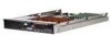
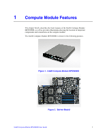
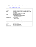
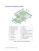
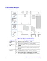
J3A3: BIOS Bank 1-2 Select 2-3 If these pins are jumpered, the BIOS will be forced to boot from the lower bank. These pins should not be jumpered for normal operation. These pins should have a jumper in place for normal system operation. (Default) Front Panel Connectors and Indicators J I AB C D E FG H AF002408 A USB1 Port C Video Connector E NIC1 and NIC2 Activity LEDs G ID LED I Fault LED B USB2 Port D I/O 1 and I/O 2 Activity LEDs F Drive Activity LED H Power Button J Power LED Figure 5. Front Panel Connectors and Indicators Hardware Requirements To avoid integration difficulties and possible board damage, your system must meet the requirements outlined below. Processor The Intel® Compute Module MFS5000SI supports up to two Multi-Core Intel® Xeon® Processors 5xxx Series. Memory A minimum of two fully-buffered DDR2 667 MHz DIMM(s) (FB-DIMM) should be installed. Additional DIMMs must be installed in pairs, up to eight total. Intel® Compute Module MFS5000SI User Guide 5
-
 1
1 -
2
-
3
-
4
-
5
-
6
-
7
-
8
-
9
-
10
-
11
-
 12
12 -
 13
13 -
 14
14 -
 15
15 -
 16
16 -
 17
17 -
 18
18 -
 19
19 -
 20
20 -
 21
21 -
 22
22 -
23
-
24
-
25
-
26
-
27
-
28
-
29
-
30
-
31
-
32
-
33
-
34
-
35
-
36
-
37
-
38
-
39
-
40
-
41
-
42
-
43
-
44
-
45
-
46
-
47
-
48
-
49
-
50
-
51
-
52
-
53
-
54
-
55
-
56
-
57
-
58
-
59
-
60
-
61
-
62
-
63
-
64
-
65
-
66
-
67
-
68
-
69
-
70
-
71
-
72
-
73
-
74
-
75
-
76
-
77
-
78
-
79
-
80
-
81
-
82
-
83
-
84
-
85
-
86
-
87
-
88
-
89
-
90
-
91
-
92
-
93
-
94
-
95
-
96
-
97
-
98
-
99
-
100
-
101
-
102
-
103
-
104
-
105
-
106
-
107
-
108
-
109
-
110
-
111
-
112
 |
 |
