Intel S3420GPLX User Guide - Page 45
Remove the Socket Protective Cover,
 |
UPC - 735858211802
View all Intel S3420GPLX manuals
Add to My Manuals
Save this manual to your list of manuals |
Page 45 highlights
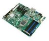
7. Remove the socket protective cover (Figure 13). REMOVE AF003188 Figure 13. Remove the Socket Protective Cover 8. Take the processor out of the box and remove the protective shipping cover (Figure 14). A AF003189 Figure 14. Remove the Processor Protective Cover 9. Align the processor cutouts to match the two socket pins, and insert the processor into the socket as shown in Figure 15. Intel® Server Board S3420GP User Guide 43
-
 1
1 -
2
-
3
-
4
-
5
-
6
-
7
-
8
-
9
-
10
-
11
-
12
-
13
-
14
-
15
-
16
-
17
-
18
-
19
-
20
-
21
-
22
-
23
-
24
-
25
-
26
-
27
-
28
-
29
-
30
-
31
-
32
-
33
-
34
-
35
-
36
-
37
-
38
-
39
-
 40
40 -
 41
41 -
 42
42 -
 43
43 -
 44
44 -
 45
45 -
 46
46 -
 47
47 -
 48
48 -
 49
49 -
 50
50 -
51
-
52
-
53
-
54
-
55
-
56
-
57
-
58
-
59
-
60
-
61
-
62
-
63
-
64
-
65
-
66
-
67
-
68
-
69
-
70
-
71
-
72
-
73
-
74
-
75
-
76
-
77
-
78
-
79
-
80
-
81
-
82
-
83
-
84
-
85
-
86
-
87
-
88
 |
 |

Intel® Server Board S3420GP User Guide
43
7.
Remove the socket protective cover (
Figure 13
).
Figure 13. Remove the Socket Protective Cover
8.
Take the processor out of the box and remove the protective shipping cover
(
Figure 14
).
Figure 14. Remove the Processor Protective Cover
9.
Align the processor cutouts to match the two socket pins, and insert the processor
into the socket as shown in
Figure 15
.
AF003188
REMOVE
AF003189
A