Intel SBT2 Product Guide - Page 26
sides of the top, until the processor is seated in the processor connector on the server board.
 |
UPC - 735858140096
View all Intel SBT2 manuals
Add to My Manuals
Save this manual to your list of manuals |
Page 26 highlights
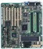
8. Clip two plastic ejectors (Figure 8, A) to the new processor (Figure 8, B). 9. Slide the new processor into the processor slot. Push down firmly, with even pressure on both sides of the top, until the processor is seated in the processor connector on the server board. A B C A. Ejectors B. Processor C. Retention wires D. Retention Mechanism Figure 8. Installing a Processor D OM10413 26 Upgrading
-
 1
1 -
2
-
3
-
4
-
5
-
6
-
7
-
8
-
9
-
10
-
11
-
12
-
13
-
14
-
15
-
16
-
17
-
18
-
19
-
20
-
 21
21 -
 22
22 -
 23
23 -
 24
24 -
 25
25 -
 26
26 -
 27
27 -
 28
28 -
 29
29 -
 30
30 -
 31
31 -
32
-
33
-
34
-
35
-
36
-
37
-
38
-
39
-
40
-
41
-
42
-
43
-
44
-
45
-
46
-
47
-
48
-
49
-
50
-
51
-
52
-
53
-
54
-
55
-
56
-
57
-
58
-
59
-
60
-
61
-
62
-
63
-
64
-
65
-
66
-
67
-
68
-
69
-
70
-
71
-
72
-
73
-
74
-
75
-
76
-
77
-
78
-
79
-
80
-
81
-
82
-
83
-
84
 |
 |

26
Upgrading
8.
Clip two plastic ejectors (Figure 8, A) to the new processor (Figure 8, B).
9.
Slide the new processor into the processor slot.
Push down firmly, with even pressure on both
sides of the top, until the processor is seated in the processor connector on the server board.
OM10413
A
C
D
B
A.
Ejectors
B.
Processor
C.
Retention wires
D.
Retention Mechanism
Figure 8.
Installing a Processor