JVC BR-DV600UA 45 pg user manual for BR-DV600U/E VTR (1130KB) - Page 11
Menu switch details
 |
View all JVC BR-DV600UA manuals
Add to My Manuals
Save this manual to your list of manuals |
Page 11 highlights
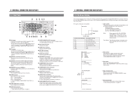
4 MENU SWITCHES 4-2 Menu switch details For switch setting procedures, refer to "Menu switch setting procedure". q: Factory setting (00): The number in the bracket shows the set value on the counter display. 002 OPERATION LOCK Details: Switches the operation lock ON/OFF. Setting: qOFF (00): The operation lock is OFF: all operations are enabled. ON (01): The operation lock is ON: all controls are disabled except for the [MENU] button. 003 SYNC SELECT Details: Selects the sync signal during play. Setting: EXTERNAL (01): Synchronizes with the signal input to the [SYNC IN] connector. qAUTO (03): Switches the synchronization automatically depending on whether or not a signal is input to the [SYNC IN] connector. For details, refer to page 11. 050 REMOTE SELECT Details: Selects the remote controller connected to the [REMOTE] connector on the rear panel. When the optional SA-K46 RS-232C interface board is installed at the [REMOTE 1] connector, some setting indications will change. Setting: IEEE 1394 (01): Allows control of this unit with the controller connected to the [DV IN/ OUT] connector. RS422A (04): Allows control of this unit with the controller connected to the [REMOTE 1] connector. IEEE 1394 + RS422A (05): Allows control of this unit with the controllers connected to the [DV IN/OUT] and [REMOTE 1] connectors. JVC BUS (08): Allows control of this unit with the controller connected to the [REMOTE 2] connector. JVC BUS + IEEE 1394 (09): Allows control of this unit with the controllers connected to the [REMOTE 2] and [DV IN/ OUT] connectors. JVC BUS + RS422A (12): Allows control of this unit with the controllers connected to the [REMOTE 2] and [REMOTE 1] connectors. qJVC BUS + RS422A + 1394 (13): Allows control of this unit with the controllers connected to the [REMOTE 2], [REMOTE 1] and [DV IN/OUT] connectors. (When the optional SA-K46 RS-232C interface board is installed) IEEE 1394 (01): Allows control of this unit with the controller connected to the [DV IN/ OUT] connector. RS232C (02): Allows control of this unit with the controller connected to the [REMOTE 1] connector. IEEE 1394 + RS232C (03): Allows control of this unit with the controllers connected to the [DV IN/OUT] and [REMOTE 1] connectors. JVC BUS (08): Allows control of this unit with the controller connected to the [REMOTE 2] connector. JVC BUS + IEEE 1394 (09): Allows control of this unit with the controllers connected to the [REMOTE 2] and [DV IN/ OUT] connectors. JVC BUS + RS232C (10): Allows control of this unit with the controllers connected to the [REMOTE 2] and [REMOTE 1] connectors. qJVC BUS + RS232C + 1394 (11): Allows control of this unit with the controllers connected to the [REMOTE 2], [REMOTE 1] and [DV IN/OUT] connectors. 108 VIDEO INPUT SELECT Details: Selects the input video signal. Setting: qLINE (00): Selects video signals input to the [LINE IN] connector. Y/C (01): Selects video signals input to the [Y/C IN] connector. COMPONENT (02): Selects video signals input to the [COMPONENT IN] connector. IEEE 1394 (03): Selects video and audio signals input to the [DV IN/OUT] connector. In this case, analog audio signals are not input. 125 SETUP (U MODEL) Details: Sets whether or not the setup is applied to the analog video signals (composite, Y/C, component). Setting: OFF (00): Does not apply the setup. q ON (01): Applies the setup. Set to this position to play back a tape recorded on the GYDV500. Notes: • This setting affects recording and playback of analog video signals. • Picture hue and brightness can be affected if dubbing is repeated without applying a setup suitable to video signals. 18 For servicing See the service manual page 1-19 "1.11 SET UP SW". ← 4 MENU SWITCHES 4-2 Menu switch details q: Factory setting (00): The number in the bracket shows the set value on the counter display. 212 AUDIO OUT AT SEARCH Details: Selects whether or not audio is output to the [AUDIO OUT] and [AUDIO MONITOR OUT] connectors and headphones jack during search at speeds above ±1x. Setting: OFF (00): No output. qON (01): Audio is output. 214 V. FADE Details: Switches the V. fade function ON/OFF. V.fade reduces audio noise at the tag recording during playback. Setting: OFF (00): The V. fade function is not activated. qON (01): Activates the V. fade function. 245 SAMPLING RATE Details: Selects the sampling rate frequency when recording audio digitally. Setting: 32K (00): Records signals at a 32 kHz sampling frequency. Set to this position for audio dubbing on CH3 and CH4. q48K (01): Records signals at a 48 kHz sampling frequency. Audio dubbing is not possible with this setting. 311 AUTO PLAY Details: Selects whether or not playback starts automatically after the tape is rewound to the beginning. Setting: qSHORT FF (00): The tape stops after short FF. Auto play does not start. PLAY (01): Auto play starts. Repeat playback is available when No. 312 menu switch is set to "ON". 312 AUTO REW Details: Selects whether or not the tape is rewound automatically at tape end during recording or playback. Setting: qOFF (00):The tape is not rewound automatically. ON (01): The tape is rewound automatically. Repeat playback is available when No. 311 menu switch is set to "PLAY". 353 EDIT ADJUST Details: When this unit is used with an editing controller and the edit-in point is shifted, this corrects the play start timing. Switch setting differs depending on the configuration of the editing system. For details, refer to "Edit adjust setting" on page 16. Setting: q0F: No compensation. 1F: The playback start point is delayed by 1 frame. 2F: The playback start point is delayed by 2 frames. 3F: The playback start point is delayed by 3 frames to the factory set timing. 4F: The playback start point is delayed by 4 frames. 5F: The playback start point is delayed by 5 frames. 6F: The playback start point is delayed by 6 frames. 7F: The playback start point is delayed by 7 frames. 360 AUTO REW AT TIMER Details: Selects whether or not the tape is automatically rewound when the VCR power is switched ON in the Timer Play or Recording Standby mode. Setting: qOFF (00): Playback or recording starts immediately. The tape is not rewound. ON (01): Playback or recording starts after the tape is rewound to the beginning. 363 CONTROLLER SELECT Details: Selects the setting according to the type of remote control unit connected via the RS422A interface. Setting: qTYPE 1 (00): For the RM-G820. TYPE 2 (01): For a non-linear editing system. TYPE 3 (02): Unused. : TYPE 8 (07) 396 BATTERY SELECT Details: When using DC power, set this switch according to the DC power supply and battery type. Setting: q12 V (00): Select this setting to use a DC power supply (AA-G10) or DC 12 V flat shape type battery. 13.2 V (01): Select this setting to use Anton Bauer Inc.'s Trimpack 13, ProPac 13. 14.4 V (02): Select this setting to use Anton Bauer Inc.'s Trimpack 14, ProPac 14 and IDX Corporation's NP-L46. 19
-
 1
1 -
2
-
3
-
4
-
5
-
 6
6 -
 7
7 -
 8
8 -
 9
9 -
 10
10 -
 11
11 -
 12
12 -
 13
13 -
 14
14 -
 15
15 -
 16
16 -
17
-
18
-
19
-
20
-
21
-
22
-
23
-
24
 |
 |
