JVC BR-DV600UA 45 pg user manual for BR-DV600U/E VTR (1130KB) - Page 5
Controls, Connectors And Displa - br dv600u vcr
 |
View all JVC BR-DV600UA manuals
Add to My Manuals
Save this manual to your list of manuals |
Page 5 highlights
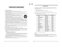
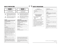
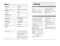
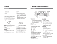
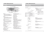
1 INTRODUCTION 1-3 Precautions Installation and storage 5 Avoid using the unit in places subject to the following conditions: - Extreme heat or cold - Strong magnetic field - High humidity - Dust and soil - Vibrations - Condensation Condensation 5 Do not use this unit immediately after moving it from a cold place to a warm place or after switching on a heater in a cold room. This will cause water vapor to condense on the video head drum and tape guides and may damage the tape and the VCR. 5 When condensation occurs, the DEW indication appears on the tape counter display and the warning indication on the on-screen display. Leave the VCR in this state with the power on and wait until the warning message turns off. Head drum Cassette tape 5 Type Only cassettes bearing the MiniDV mark can be used with this VCR. 5 Handling • Cassette tapes cannot be loaded upside-down. • Rewind the tape to the beginning before storage. • The number of times a tape can be reused is limited. If the tape is reused more than this, increased noise (such as dropouts) may result. Do not use dirty or damaged tapes. Doing so not only results in poorer performance, but may also shorten the service life of the rotary heads. • It is possible that some distortion may occur at the beginning and end of tapes. This can vary depending on the tape. However, for best results, do not use these sections of the tape for any important recordings. Erasure prevention MiniDV cassettes are provided with a safety slide on the side to prevent accidental erasure. Set it as required. Video tape Handling 5 Do not block the ventilation openings. 5 Do not place anything heavy on the unit. 5 Do not put any foreign materials into the cassette loading slot. 5 Operate the unit in a horizontal (flat) position only. 5 Avoid violent shocks to the unit. Transportation 5 Remove the cassette tape from the unit prior to trans- portation. Energy saving 5 When not using the unit, turn the power off to avoid unnecessary power consumption. REC SAVE Safety slide • Move the slide to SAVE to prevent erasure. • Move the slide to REC to allow recording. Power supply 5 This unit is provided with both AC and DC power supplies. For editing over an extended period, it is recommended that you use a stable AC power supply or DC power supply from an AC adapter. Using battery power is recommended only as a supplementary power source or for field use. 5 The AC and DC power supplies are switched automatically. When the AC power supply is switched to the DC power supply, the power turns off. When both power supplies are connected, the AC power supply has priority. Be sure to confirm which power supply is in use when plugging or unplugging the power supply. 6 2 CONTROLS, CONNECTORS AND DISPLAYS 2-1 Front Panel #$ % OPERATE CH-1/3 VIDEO CASSETTE RECORDER BR-DV600U ON/OFF 1 @ REC LEVEL EJECT 2 MENU ADVANCE PRESET CH-2/4 REC PLAY PAUSE ! 0 SHIFT SHIFT HOLD SHIFT A. DUB PHONES SELECT SET MONITOR OUTPUT COUNTER L CH-1/2 CTL MIX MIX TC R CH-3/4 UB CH 1/3 40 30 20 10 CH 2/4 32k 48k SLAVE AUD LOCK SP OVER AUTO OFF DEW 0 dB OVER SERVO RF PB NDF HOLD MENU H M S F REMOTE REW STOP FF LOCAL MIC 3 4 AUDIO 987 6 5 1 [OPERATE] switch Press this switch to turn this unit ON. Press it again to turn this unit OFF. When the power is OFF, the "oPE-oFF" indication is shown. Keep in mind that a small amount of current continues to flow into the VCR even when the power is turned off. When not using this unit, disconnect the power cable from the AC outlet. Remove the battery when not in use to avoid excessive discharge. 2 [EJECT] button Press to eject the cassette. 3 [REMOTE/LOCAL] switch Use to switch between REMOTE and LOCAL. 4 [MIC] jack Connect a microphone (3.5 mm dia., -67 dBs, 3 kΩ). 5 Operation buttons Use to control tape running. REC: Recording PLAY: Playback PAUSE: Temporary stop REW: Rewinding STOP: Stop FF: Fast-forwarding 6 LCD Display Use to show various data including the tape counter and audio level meter. For details, refer to "LCD display" on page 10. 7 [COUNTER] switch Use to switch the type of data displayed on the tape counter. When the No. 516 menu switch is set to "CLOCK", clock is shown for TC and date is shown for UB. 8 [AUDIO OUTPUT] switch Use to select the audio channel to output from the rear panel's [AUDIO OUT] connectors and the headphones. 9 [AUDIO MONITOR] switch Use to select the audio channel to output from the rear panel's [AUDIO MONITOR OUT] connectors. 0 [PHONES] jack Connect a set of headphones (3.5 mm dia. mini-jack). ! PHONES control Use to adjust the volume level of the headphones connected to the PHONES jack. @ [REC LEVEL] control Use to adjust the audio recording level. CH-1/3: CH1 can be adjusted in normal recording. CH3 recording level can be adjusted in audio dubbing. CH-2/4: CH2 can be adjusted in normal recording. CH4 recording level can be adjusted in audio dubbing. Audio dubbing is possible when the No. 245 menu switch is set to "32K". # Setting buttons Use to set the menu switch, time code and user bits. Menu switch setting MENU: Press to set the menu switch setting mode. SHIFT +/-: Use to select the menu switch. SET: Use to enter the set value. SELECT: Use to change the value. Time code and user bits setting HOLD: Press to set the time code, user bits or time date setting mode. SHIFT: Use to select the digit whose value is to be changed. ADVANCE: Use to change the value. While pressing the [SHIFT] button, press this button to reset the set data to "0". PRESET: Use to enter the changed value and end setting. Use as a counter reset button when the [COUNTER] switch is set to "CTL". $ [AUDIO DUB] button Use to perform audio dubbing when the No. 245 menu switch is set to "32K". % Cassette loading slot Load and unload a cassette. 7
-
 1
1 -
 2
2 -
 3
3 -
 4
4 -
 5
5 -
 6
6 -
 7
7 -
 8
8 -
 9
9 -
 10
10 -
 11
11 -
12
-
13
-
14
-
15
-
16
-
17
-
18
-
19
-
20
-
21
-
22
-
23
-
24
 |
 |
