JVC BR-DV600UA 45 pg user manual for BR-DV600U/E VTR (1130KB) - Page 8
Audio system connections, Other connections - pro
 |
View all JVC BR-DV600UA manuals
Add to My Manuals
Save this manual to your list of manuals |
Page 8 highlights
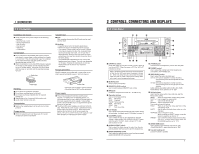
3 CONNECTIONS 3-2 Audio system connections Audio output from a VCR, etc. DV Analog audio (2 channels) DV IN/OUT VIDEO LINE COMPONENT Y/C IN R-Y B-Y Y AUDIO CH 1/3 CH 2/4 IN IN OUT OUT OUT MONITOR OUT 1 REMOTE 2 MONITOR OUT SYNC IN TIME CODE SPARE TIMER SERIAL REC PLAY DC 12V OFF Headphones Mic DV Analog audio (2 channels) Audio input to a VCR, etc. Analog audio (monaural) Connection with a monitor TV The audio output from the [AUDIO MONITOR OUT] connector is monaural. Use the front panel [AUDIO MONITOR] switch to select the audio channels you want to monitor. The selected audio channel is shown in the table below. Adjust the audio volume level on the monitor. Headphones jack Audio can be monitored in stereo using the headphones. Use the front panel [AUDIO OUTPUT] switch to select the audio channels you want to monitor. The selected audio channel is shown in the table below. Adjust the audio volume level with the front panel [PHONES] control. Inputs 5 Analog inputs Audio connectors (CH1/3, CH2/4) Analog input connectors are only provided for 2 channels. It is not possible to record 4 channels simultaneously. Audio input from each connector is normally recorded on the CH1 and CH2 channels. Recording on the CH3 and CH4 can be performed in the Audio Dubbing mode with the No. 245 menu switch set to "32K". For audio dubbing, refer to "Audio dubbing" on page 24. 5 Digital inputs Digital signals conforming to IEEE 1394 can be input to the [DV IN/OUT] connector. In this case, the audio recording level cannot be adjusted. When audio signals are input to the [DV IN/OUT] connector, some noise will occur at the point where recording ends. To reduce this noise during playback, set the No. 214 menu switch to "ON". 5 Mic input jack Connect a monaural microphone. The same audio is recorded on both channels. 12 Monitor TV Outputs 5 Analog outputs Audio connectors (CH1/3, CH2/4) Analog output connectors are provided for 2 channels. For MiniDV format, use the front panel [AUDIO OUTPUT] switch to select for 4-channel audio. The selected audio channel is shown in the table below. 5 Digital outputs Digital signals conforming to IEEE 1394 are output from the [DV IN/OUT] connector. Relationship between [AUDIO OUTPUT] / [AUDIO MONITOR] switch and audio output channel (During playback with 32 kHz sampling, audio dubbing, and DV input with the 32 kHz sampling in the EE mode) Regardless of setting of this switch, CH1/2 is selected for ordinary recording, record pause and analog audio input in the EE mode. CH3/4 is selected for audio dubbing in the Pause mode. AUDIO switch MONITOR OUTPUT CH1/2 MONITOR OUT CH1 Connector AUDIO OUT CH1/3 CH2/4 CH1 CH2 L MIX CH1/3 CH1/3 CH2/4 CH3/4 CH1/2 CH3 CH1/2 CH3 CH1 CH4 CH2 MIX MIX CH1/2/3/4 CH1/3 CH2/4 CH3/4 CH1/2 CH3/4 CH2 CH3 CH1 CH4 CH2 R MIX CH3/4 CH2/4 CH4 CH1/3 CH3 CH2/4 CH4 PGZ01945 PGZ01945 3 CONNECTIONS 3-3 Other connections DV IN/OUT Y/C VIDEO LINE IN COMPONENT R-Y B-Y Y AUDIO CH 1/3 CH 2/4 IN IN OUT OUT OUT MONITOR OUT 1 REMOTE 2 MONITOR OUT SYNC IN TIME CODE SPARE TIMER SERIAL REC PLAY DC 12V OFF 12 34 5 Remote connector Connect a remote controller to the appropriate connector (three types are available). Type of connector 1 [SERIAL] connector 2 [REMOTE1] connector 3 [REMOTE2] connector Connectable remote controller RM-G30 RM-G820 RM-G800 Note: • Before connecting the RM-G800, be sure to turn the VCR OFF. Do not connect or disconnect the remote cable with the VCR ON. Power sockets 2 types of power supply are available (AC, DC). 4 DC power supply socket Connect DC 12 V. 5 AC power supply socket Connect AC 120 V (U MODEL), AC 220 - 240 V (E MODEL). 5 Selection of battery type Set the menu switch according to the type of battery that will be used. * If the setting does not correspond to the battery type, the battery remaining time and battery alarm will not be correctly displayed. Note: • Do not use this unit continuously when the battery indicator is displayed. The unit may not operate properly. Remove the battery to avoid overdischarge. ੬ See "396 BATTERY SELECT" on page 19. • Used battery The following batteries can be used with this unit. • Flat shape type • Anton Bauer Inc. : Trimpack 13 and 14 series Pro Pac 13 and 14 series • IDX Corporation : NP-L46 13
-
 1
1 -
2
-
 3
3 -
 4
4 -
 5
5 -
 6
6 -
 7
7 -
 8
8 -
 9
9 -
 10
10 -
 11
11 -
 12
12 -
 13
13 -
14
-
15
-
16
-
17
-
18
-
19
-
20
-
21
-
22
-
23
-
24
 |
 |
