JVC GY-HD250U 117 page operator's manual for the GY-HD250U
JVC GY-HD250U - 3-ccd Prohd Camcorder Manual
 |
UPC - 046838027383
View all JVC GY-HD250U manuals
Add to My Manuals
Save this manual to your list of manuals |
JVC GY-HD250U manual content summary:
- JVC GY-HD250U | 117 page operator's manual for the GY-HD250U - Page 1
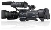
possible performance. For Customer Use: Enter below the Serial No. which is located on the body. Retain this information for future reference. Model No. Serial No. * The illustration shows the GY-HD250/GYHD251 HD CAMERA RECORDER with the provided lens, viewfinder and microphone attached. LST0440 - JVC GY-HD250U | 117 page operator's manual for the GY-HD250U - Page 2
outlet, consult an electrician for replacement of the obsolete outlet. 10. Protect the power cord from being walked on or pinched particularly at plug, convenience receptacles, and the point where they exit from the apparatus. 11. Only use attachments/accessories specified by the manufacturer. 12 - JVC GY-HD250U | 117 page operator's manual for the GY-HD250U - Page 3
and fire hazards, do NOT use any other power source. NOTE: The rating plate (serial number plate) is on the bottom of the unit. CAUTION: To prevent electric shock, do not open the cabinet. No user serviceable parts inside. Refer servicing to qualified service personnel. AVERTISSEMENT : POUR EVITER - JVC GY-HD250U | 117 page operator's manual for the GY-HD250U - Page 4
and fire hazards, do NOT use any other power source. NOTE: The rating plate (serial number plate) is on the bottom of the unit. CAUTION: To prevent electric shock, do not open the cabinet. No user serviceable parts inside. Refer servicing to qualified service personnel. Due to design modifications - JVC GY-HD250U | 117 page operator's manual for the GY-HD250U - Page 5
please contact your local municipal office, your household waste disposal service or the shop where you purchased the product. Penalties may with national legislation. (Business users) If you wish to dispose of this product, please visit our web page www.jvc-europe.com to obtain information - JVC GY-HD250U | 117 page operator's manual for the GY-HD250U - Page 6
the JVC GY-HD250U/CHU and GY-HD251E/CHE HD CAMERA RECORDER. These instructions are for the GY-HD250U/CHU and GYHD251E/CHE. • A lens is included with the GY-HD250U and GY-HD251E. • A lens is not included with the GY-HD250CHU and GY- HD251CHE. Information applicable only to the GY-HD250U/CHU - JVC GY-HD250U | 117 page operator's manual for the GY-HD250U - Page 7
play back HD (High Definition) video on Mini DV videocassettes. There are two types of recording formats within HDV format. HDV 720p (720 effective scan lines, progressive scan) HDV 1080i (1080 effective scan lines, interlaced scan) GY-HD250/GY-HD251 supports HDV 720p format. (HDV 720p) HDV and - JVC GY-HD250U | 117 page operator's manual for the GY-HD250U - Page 8
Maintenance 7 Precautions for Use of Head Cleaning Tape 7 Battery Pack to be Used 8 Videocassette to be Used 8 For recording and storing videotapes in the best condition . . . 8 Condensation 9 Characteristic CCD Phenomena 9 CONTROLS, INDICATORS AND CONNECTORS ZOOM Lens 10 Front Section 11 - JVC GY-HD250U | 117 page operator's manual for the GY-HD250U - Page 9
(formatting) an SD memory card 102 FEATURES OF THE CAMERA SECTION How to Use Skin Detail 103 Outputting Color Bars 105 OTHERS Warnings and Responses 106 Troubleshooting 110 How to Display the Hour Meter 111 Specifications 112 EXTERNAL DIMENSIONS 113 MENU SCREENS Menu Screen Configuration - JVC GY-HD250U | 117 page operator's manual for the GY-HD250U - Page 10
Proper Use • Supply voltage Make sure that the power is between 11 V and 15 V DC. If the power voltage used near the camera during recording, the tuner could pick up noise. • Avoid using or placing this device in places; • subject to extreme heat or cold; • with excessive dirt or dust; • with high - JVC GY-HD250U | 117 page operator's manual for the GY-HD250U - Page 11
REQUIRED!" is displayed on the LCD monitor, and in the viewfinder during playback and recording check using the RET button on the lens section. Periodical Maintenance Contents : Check or replace the following mechanical parts according to the running time. Usage Time 500H 1000H Drum assembly - JVC GY-HD250U | 117 page operator's manual for the GY-HD250U - Page 12
U model: Dionic 90 (Anton Bauer) E model: Endura-7 (IDX) CAUTION Use only the recommended batteries. If a heavy battery is used, the battery may fall out depending on the way the HD camera recorder is used. Videocassette to be Used • Use JVC's videocassette tapes marked with the A symbol. • Mini DV - JVC GY-HD250U | 117 page operator's manual for the GY-HD250U - Page 13
White dots High temperatures can cause CCD sensor pixels to CCD). As far as possible, use this device under conditions where the temperature of this device does not increase. Keep the power on until the warning message disappears. If the power into frost. In such a case, it takes an additional 23 - JVC GY-HD250U | 117 page operator's manual for the GY-HD250U - Page 14
3:11 PM CONTROLS, INDICATORS AND CONNECTORS ZOOM Lens The zoom lens is not provided with the GY-HD250CHU or the GY-HD251CHE. Th16 × 5.5BRMU 32 1 RET M A W T 4 5 6 78 9 0 d MACRO ab c 1FOCUS ring Manual focus ring. 2ZOOM lever/ring This is the manual zoom ring equipped with a zoom - JVC GY-HD250U | 117 page operator's manual for the GY-HD250U - Page 15
page 33. 4Front tally lamp This lamp lights up when the GY-HD250/GY-HD251 enters the record mode. It blinks during the transition to the record mode. When the tape has run out, or the VTR enters the warning mode, it blinks quickly. • Use the FRONT TALLY item on the OTHERS[1/2] menu screen to select - JVC GY-HD250U | 117 page operator's manual for the GY-HD250U - Page 16
figure. 1 2 3 4 1Back tally lamp This lamp lights up when the GY-HD250/GY-HD251 enters the record mode. It blinks during the transition to the record mode. When the tape has run out, or the VTR enters the warning mode, it blinks quickly. • Use the BACK TALLY item on the OTHERS[1/2] menu screen to - JVC GY-HD250U | 117 page operator's manual for the GY-HD250U - Page 17
the mode is being switched : Flashing In VTR mode : Lit In camera mode : Off • Select the Camera mode to record the camera image. • Select the VTR mode to playback VTR or to input the HDV/DV signal from the IEEE1394 connector 0 on page 16. • When the power is turned on, the mode becomes the - JVC GY-HD250U | 117 page operator's manual for the GY-HD250U - Page 18
USER 2 USER 3 ND FILTER 2 1 MENU STATUS WHT.BAL AUTO AUTO AUDIO CH-1 LEVEL CH-2 ON OFF POWER REC de fg i h 1Monitoring speaker (Cheek pad) • In the Camera mode, the input sound can be EE monitored. In the VTR mode, the speaker outputs the VTR playback sound. In the VTR mode, the HDV - JVC GY-HD250U | 117 page operator's manual for the GY-HD250U - Page 19
. * Wait at least 5 seconds if you need to turn the power on again. e[REC] REC trigger button (start/stop recording) Start and stop recording using this button. (This works together with the REC trigger button on the top and the lens VTR trigger button.) When "SPLIT" is set for the 1394 REC - JVC GY-HD250U | 117 page operator's manual for the GY-HD250U - Page 20
Camera mode. • Outputs the playback audio signal in the VTR mode. • When a HDV/DV signal (IEEE1394) is input, the EE sound of the input audio signal is output in the VTR mode. MEMO Alarm sound is not output. 0[IEEE1394] IEEE1394 connector (6-pin) Using an IEEE1394 cable (optional), a digital video - JVC GY-HD250U | 117 page operator's manual for the GY-HD250U - Page 21
a studio camera. For details, refer to the KA-HD250 INSTRUCTION MANUAL. b[DC INPUT] DC input terminal (XLR 4-pin) This is the 12V DC power input terminal. Connect to the AC adapter. When a battery is installed and a cable is connected to this terminal, power supply from the battery stops and power - JVC GY-HD250U | 117 page operator's manual for the GY-HD250U - Page 22
as the FOCUS ASSIST button 6 in the Right Side Section. X See "LCD/VF[1/4] Menu Screen" on page 89. 8[REC] REC trigger button (start/stop recording) Start and stop recording using this button. (This works together with the REC trigger button on the right panel and the lens VTR trigger button - JVC GY-HD250U | 117 page operator's manual for the GY-HD250U - Page 23
can be used to camera is in the VTR mode. To perform VTR playback or to input the HDV manual adjustment mode for audio recording level. X See "AUDIO/MIC[2/2] Menu Screen" on page 88. • Even if there are color bars, this automatically sets to camera video. • Auto iris mode operates even if the lens - JVC GY-HD250U | 117 page operator's manual for the GY-HD250U - Page 24
Recording and Image Output Formats This device supports HDV recording camera images HD (HDV) DV HD Recording (Shooting) [REC] menu item Format HDV-HD60P 720/60p HDV-HD30P 720/30p HDV-HD50P 720/50p HDV-HD25P 720/25p HDV SDI Out [HDV PB OUTPUT] menu item 720P 1080I NTSC HDV 720/60p - JVC GY-HD250U | 117 page operator's manual for the GY-HD250U - Page 25
24, 2006 3:11 PM „ When Recording HDV or DV Images from the IEEE1394 Terminal HDV Recording (IEEE1394 In) 720/60p 720/30p 720/50p 720/25p 720/24p Rec on Tape q q q q q NATIVE q 720/60p q 720/50p 720/60p Component / SDI Out [HDV PB OUTPUT] menu item 720P q q q q q 1080I 1080/60i 1080/60i - JVC GY-HD250U | 117 page operator's manual for the GY-HD250U - Page 26
picture, the LCD monitor and viewfinder are also used for the following character displays. To show characters on CAMERA MODE (display example) STATUS 0 STATUS 1 DISPLAY button „ Status screens (screens for checking the current camera settings) „ Auto white display (only displayed in the Camera - JVC GY-HD250U | 117 page operator's manual for the GY-HD250U - Page 27
11 PM Status Screens in the Camera Mode 1 0 266S DD 9 8 7 6 5 4 External Image Input Mode (AUX IN) a 0 DV-60I AUX 266S DD 1 2 3 STATUS 0 Screen 2 3 STATUS 0 Screen STATUS 0 1 Event Indication When the Gain or Shutter Speed is changed manually, the setting condition is displayed for - JVC GY-HD250U | 117 page operator's manual for the GY-HD250U - Page 28
FAW operation FAW : Indicated when Full Auto White Balance is ON. 8 Gain operation FOCUS enhancements) is connected, its operation status is displayed. ation [: DR-HD100 is connected (displays white) [: Recording with DR-HD100 (displays red) (For details, refer to the DR-HD100 INSTRUCTION MANUAL - JVC GY-HD250U | 117 page operator's manual for the GY-HD250U - Page 29
See page 91. Whether the time code or user's bits should be shown is selected with the to be regarded only as a guide. * When this device is used at low temperatures, it may take battery level in 0.1V steps. Battery voltage and remaining battery are displayed. Select the display method in BATTERY - JVC GY-HD250U | 117 page operator's manual for the GY-HD250U - Page 30
/MIC[1/2] menu screen is set to 48 K. (Audio is recorded with 16-bit, 48 kHz sampling.) When HDV format is set, 48K is displayed. X See page 87. Indicates the F-number of the connected lens. OPEN, F2, F2.8, F4, F5.6, F8, F11, F16, CLOSE It is not displayed when the lens is removed. For some lenses, - JVC GY-HD250U | 117 page operator's manual for the GY-HD250U - Page 31
camera setup statuses. Event display is not available while this screen is displayed. STATUS 3 Screen Indication FILE FULL AUTO [##00K], FAW, MANUAL (Only when the remote control unit is used) For A and LENS RET NONE, BARS, PRESET TEMP., B.STRETCH1 to 5, B.COMPRESS1 to 5, RET, LOAD FILE RET, FOCUS - JVC GY-HD250U | 117 page operator's manual for the GY-HD250U - Page 32
HDV/DV input signal. You can switch this display ON/OFF using the VIDEO FORMAT item on the LCD/VF[1/2] menu screen. X See page 91. 2 Time code (TC) and user's bits Displays the time code data being recorded indication is to be used only as a guide. * When this device is used at low temperatures, - JVC GY-HD250U | 117 page operator's manual for the GY-HD250U - Page 33
battery: Voltage/remaining capacity (%)/remaining time IDX Endura battery : Voltage/remaining capacity (%) Displayed when the audio signal from DV recording by FOCUS enhancements) is connected, its operation status is displayed. ation (For details, refer to the DR-HD100 INSTRUCTION MANUAL.) MEMO - JVC GY-HD250U | 117 page operator's manual for the GY-HD250U - Page 34
Auto White Balance Indication (Camera mode only) The AUTO WHITE indication and the result of the operation are displayed during the auto 108. Alarm display area Menu Setting Screen Screen used for making various settings. The Menu Setting HDV-HD60P HDV-HD50P HDV-HD30P HDV-HD25P HDV-HD24P [16:9] 30 - JVC GY-HD250U | 117 page operator's manual for the GY-HD250U - Page 35
Page 31 Tuesday, October 24, 2006 3:11 PM SAFETY ZONE CENTER MARK DV-60I DV-50I 4:3 DV-24P DV-24PA DV-25P 16:9 HDV-HD60P HDV-HD50P HDV-HD30P HDV-HD25P HDV-HD24P [16:9] 2.35:1CE OFF ON Cannot be selected 2.35:1CH OFF ON Switching between the LCD Screen and Viewfinder Display „ When - JVC GY-HD250U | 117 page operator's manual for the GY-HD250U - Page 36
PRESET AUTO MANU POWER I DOWN UP DOWN UP O CLOSE OPEN Camera Remote Control Unit RM-P210 View Finder DM-3106 (Astrodesign) V-R70P-HAD (Marshall Electronics) Studio Kit KA-HD250 *1 An HZ-FM13 cannot be used with a Th16 × 5.5BRMU or S14 × 7.3B12/U zoom lens. Use a FUJINON focus manual unit - JVC GY-HD250U | 117 page operator's manual for the GY-HD250U - Page 37
in the lens dropping off or disturbed back focus. • Set the GY-HD250/GY-HD251's power switch to "OFF" before the zoom lens is attached input connector on the GY-HD250/GY-HD251. 5. Attach the microphone cable to the clamp. 6. Make sure to perform the correct setting for use of a phantom microphone. - JVC GY-HD250U | 117 page operator's manual for the GY-HD250U - Page 38
straight out. Core filter (black) Inserting an SD Memory Card By using an SD memory card, you can save and call up menu settings and camera settings for GY-HD250/GY-HD251. X See "FILE MANAGE Menu Screen" on page 100. Check that the POWER switch is OFF. Inserting an SD Memory Card 1. Open the SD - JVC GY-HD250U | 117 page operator's manual for the GY-HD250U - Page 39
4. Hold the camera on the top and slide forward so that the base mount of the camera is locked by the front mount clip of this device as it clicks into place. 4. MACRO VF BRIGHT USER 1 USER 2 USER 3 ND FILTER 2 1 MENU STATUS WHT.BAL AUTO AUTO AUDIO CH-1 LEVEL CH-2 ON OFF POWER REC 35 - JVC GY-HD250U | 117 page operator's manual for the GY-HD250U - Page 40
cable DC OUTPUT Clamp filter AC adapter 2. Press the POWER switch of the GY-HD250/GY-HD251 to ON. Power is supplied to the VTR section and the camera. CAUTION • Do not remove or connect the DC cable while recording is being performed. • Do not use any power source with large fluctuations in the - JVC GY-HD250U | 117 page operator's manual for the GY-HD250U - Page 41
battery is used, the battery may fall out depending on the way the HD camera recorder is used. „GY-HD250U Use an Anton Bauer battery. „GY-HD251E Use an IDX (Endura) battery. Attaching the Battery 1. Face the battery terminals down and align the battery V- mount with the battery adapter V-mount - JVC GY-HD250U | 117 page operator's manual for the GY-HD250U - Page 42
ON again. • If the GY-HD250/GY-HD251 is left with the battery pack attached, a small amount of power is consumed even if the POWER switch on the GY-HD250/GY-HD251 is set to OFF. Remove the battery pack when the GY-HD250/GY-HD251 is not going to be used. Remaining Battery Power Display LCD monitor - JVC GY-HD250U | 117 page operator's manual for the GY-HD250U - Page 43
In VTR mode : Lit In Camera mode : Off Turning the Power OFF 1. Place the GY-HD250/GY-HD251 in the record-standby or STOP mode. 2. Set the POWER switch to OFF. 3. Remove the battery pack or the power supply to the DC INPUT connector. (When the camera is not going to be used for a longer period - JVC GY-HD250U | 117 page operator's manual for the GY-HD250U - Page 44
the Cassette Cassette Loading Use a videocassette tape marked MiniDV. • To record, slide the switch on the back for use in prevent- ing accidental Inner cover „ If the power is on, the modes are as shown below. MODE Camera VTR REC/SAVE switch REC SAVE Record-standby mode STOP mode REC - JVC GY-HD250U | 117 page operator's manual for the GY-HD250U - Page 45
1 USER 2 USER 3 ND FILTER 2 1 MENU STATUS WHT.BAL AUTO AUTO AUDIO CH-1 LEVEL CH-2 ON OFF POWER REC 1. POWER switch 3. Rotate the SHUTTER dial to align the cursor (K) with the TC/UB/CLOCK item, and then press the SHUTTER dial in the direction of the camera body. • The TC/UB/CLOCK menu - JVC GY-HD250U | 117 page operator's manual for the GY-HD250U - Page 46
minutes. The digits indicating seconds screen, use either of Camera mode : The date and time of the internal clock are displayed. In VTR playback mode : The date and time recorded on the tape are displayed. In VTR stop mode : The last read date and time values are displayed. When an HDV - JVC GY-HD250U | 117 page operator's manual for the GY-HD250U - Page 47
-HD250/GY-HD251 records SMPTE-standard (NTSC) or EBU-standard (PAL) time codes and user's bits. In the play mode or the record mode, the reproduced time codes or user's bits are shown on the LCD monitor or in the viewfinder. • Time code generator data is output from the [TC OUT] ter- minal or [HD/SD - JVC GY-HD250U | 117 page operator's manual for the GY-HD250U - Page 48
in the time code generator runs only during recording. Use this setting if it is necessary to record continual time codes across different scenes. * However CLOCK menu screen (FRAME RATE: 50/25) Whether or not user's bit data should be recorded can be selected with the UB REC item on the TC/UB - JVC GY-HD250U | 117 page operator's manual for the GY-HD250U - Page 49
for setting is the same as the method for setting the time code described on the left. • The user's bit can be specified using numerals or alpha- betic letters from 0 to F for each digit. • To record user's bit data, set the UB REC item to ON (Only when set to FRAME RATE 50/25). CAUTION - JVC GY-HD250U | 117 page operator's manual for the GY-HD250U - Page 50
ON. • Menu screen is displayed. • RECORDING mode is active. • Switching to CAM/ USER 1 USER 2 USER 3 ND FILTER 2 1 MENU STATUS WHT.BAL AUTO AUTO AUDIO CH-1 LEVEL CH-2 ON OFF POWER REC USER 2 button USER 1 button USER 3 button USER 1 USER 2 USER change the blinking digit. 3Repeat steps - JVC GY-HD250U | 117 page operator's manual for the GY-HD250U - Page 51
on Tape The GY-HD250/GY-HD251 also incorporates a time code reader. Therefore, when this device enters record mode from record-standby mode, it can read the time code data recorded on the tape and record time codes in continuation of the existing data. The recorded user's bit data are identical - JVC GY-HD250U | 117 page operator's manual for the GY-HD250U - Page 52
terminal IEEE1394 cable VF BRIGHT USER 1 USER 2 USER 3 ND FILTER 2 1 MENU STATUS WHT.BAL AUTO AUTO AUDIO CH-1 LEVEL CH-2 ON OFF POWER REC IEEE1394 terminal Slide the IEEE1394 switch to the [DV] side. You can use the GY-HD250U, GY-HD251E, GY-HD110U, or GY-HD111E as a slave unit - JVC GY-HD250U | 117 page operator's manual for the GY-HD250U - Page 53
of this device. Use BB signals or Tri-sync HD signals as the external synchronization signals. CAUTION When the power switch is turned on If a time code generator is connected or disconnected during recording, servo lock will be disturbed. • The user's bit data range for an input external time code - JVC GY-HD250U | 117 page operator's manual for the GY-HD250U - Page 54
viewed from the lens side (vertically inverted image). PEAKING volume LCD BRIGHT button 180° up LCD - BRIGHT + AUDIO SELECT CH-1 CH-2 AUTO MANU CAM/VTR and angle of the viewfinder. Diopter Adjustment Rotate the eyepiece focusing ring until the viewfinder screen image is clearly visible. - JVC GY-HD250U | 117 page operator's manual for the GY-HD250U - Page 55
-angle positions. • It is easier to adjust back focus when the subject is more than 3 meters from the camera. The optimal subject for this adjustment is a Siemens star chart. 3 4, 6 5 1. Set the IRIS mode switch to M (Manual). 2. Set the zoom mode to M (Manual). 3. Open the iris by turning the iris - JVC GY-HD250U | 117 page operator's manual for the GY-HD250U - Page 56
AUTO A and AUTO B. Adjustment procedure 1. Set the following switches. • Set the POWER switch to ON. • Set the IRIS mode switch of the lens to A (Auto). • Set the FULL AUTO suitable. Replace the color temperature conversion filter or use another white Do not adjust using any highly reflective objects, - JVC GY-HD250U | 117 page operator's manual for the GY-HD250U - Page 57
balance the camera. 2. Set the camera's lens controls as follows: a. Set the IRIS opening to F4 or greater number. b. In the case of a zoom lens set the and the setting is changed. 2 Perform the above steps to set SHADING to MANUAL. 3 Select LEVEL R, LEVEL G, LEVEL B and press the SHUTTER dial. • - JVC GY-HD250U | 117 page operator's manual for the GY-HD250U - Page 58
using the same steps as for the FRAME RATE item. MEMO • If you change the FRAME RATE item setting, the system is rebooted. • The synchronous video signal is momentarily disturbed when the REC item setting is switched. • We recommend the following settings for REC item (in HDV format). When recording - JVC GY-HD250U | 117 page operator's manual for the GY-HD250U - Page 59
1 USER 2 USER 3 ND FILTER 2 1 MENU STATUS WHT.BAL AUTO AUTO AUDIO CH-1 LEVEL CH-2 ON OFF POWER REC LCD BRIGHT - + CAM/VTR AUDIO SELECT CH-1 CH-2 AUTO MANU TC DISPLAY TC UB GENE. FREE REC REGEN CAM/VTR button Screen Size (4:3/16:9) Mode Selection The screen size of recorded - JVC GY-HD250U | 117 page operator's manual for the GY-HD250U - Page 60
require +48 V power supply, make sure that the switch is not set to MIC+48V before the component is connected. 56 Adjusting Audio during Recording For each audio channel, use the CH-1/CH-2 AUDIO SELECT switch to select whether the audio level adjustment should be set to AUTO mode or MANUAL mode - JVC GY-HD250U | 117 page operator's manual for the GY-HD250U - Page 61
manual adjust mode. Recording level is suppressed • In the FULL AUTO mode, the audio HIGH) Monitoring Audio during Recording The audio input during recording, in record case of an abnormal condition occurring in this device. An alarm tone is also output when the tape end is reached or when the battery - JVC GY-HD250U | 117 page operator's manual for the GY-HD250U - Page 62
device turns on in camera mode. 2. Start recording. Press the REC/VTR trigger button on the GY-HD250/GYHD251 to start recording. Once recording has started, the FRONT TALLY lamp and BACK TALLY lamp light red. FRONT TALLY lamp FOCUS ASSIST button REC trigger button POWER switch REC trigger button - JVC GY-HD250U | 117 page operator's manual for the GY-HD250U - Page 63
content recorded in DV format and up to about 20 seconds of content recorded in HDV format camera will automatically return to recording mode after playback. CAUTION • This function does not work when using RET button is used as FOCUS ASSIST button. • This function does not work when the GY-HD250 - JVC GY-HD250U | 117 page operator's manual for the GY-HD250U - Page 64
Color bar video signal Test tone (1 kHz) (Setting range: 0 to 99 sec) Time code, user's bits recording Black video signal Mute audio (No sound) (Setting range: 0 to 99 sec) Time code, user's bits recording Time code: The value specified on the HEADER REC menu screen- HEADER REC time. (Example) 23 - JVC GY-HD250U | 117 page operator's manual for the GY-HD250U - Page 65
be the user's bits value set on the TC/UB/ CLOCK menu screen. • The running of the time code following completion of HEADER REC recording will be in accordance with the setting of the TC GENE. switch. FREE RUN : Continuous running. REC RUN or REGEN: Runs only during REC. • Camera images are - JVC GY-HD250U | 117 page operator's manual for the GY-HD250U - Page 66
GY-HD250/GY-HD251 can play back the following two types of videocassettes: • MiniDV videocassette • DVCAM videocassette Tapes recorded in the LP mode cannot be played back. 1. Set the POWER the camera image is when used in Block noise may appear in the picture or the image may freeze during the - JVC GY-HD250U | 117 page operator's manual for the GY-HD250U - Page 67
32 kHz sampling frequency is employed. The GY-HD250/GY-HD251 records audio on the two channels CH-1 and CH-2. (4-channel recording is possible in the case of DV input.) When the GY-HD250/GY-HD251 is used for playback of a tape that was recorded on another unit with audio recorded on the CH-3 and CH - JVC GY-HD250U | 117 page operator's manual for the GY-HD250U - Page 68
IEEE1394 switch on the left panel of this device. DV HDV : DV format : HDV format IEEE1394 switch Clamp filter Displaying Alarms • CHANGE 1394 Camcorder, VCR and other IEEE1394 device, make sure the following instructions, otherwise the IEEE1394 circuit device may be destroyed. • Turn the power - JVC GY-HD250U | 117 page operator's manual for the GY-HD250U - Page 69
no jitter. Input level: 1.0V ± 0.3V (p-p) Setting „ Set this device to camera mode: If the VTR indicator is lit, press the [CAM/VTR] button and turn • Recording cannot be checked using the lens RET button when recording external image signals. • Do not touch GENLOCK/AUX IN switch during recording. - JVC GY-HD250U | 117 page operator's manual for the GY-HD250U - Page 70
and you can enter recording mode. 66 IEEE 1394 CH2-AUDIO OUT-CH1 VIDEO Synchronized Signals The synchronized signal differs depending on the input sync signal. Refer the table below. Terminal Video signal VIDEO Composite SD Component HD Component 720p Y/PB/PR HD Component 1080i SD RGB - JVC GY-HD250U | 117 page operator's manual for the GY-HD250U - Page 71
-HD250/GY- HD251 to start playback. 8. Start recording on the recording unit. For details, see the instructions to the unit used for recording. 9. When dubbing is completed. Stop recording on the recording unit, and then press the STOP button on the GY-HD250/GY-HD251 to stop play- back. • HDV - JVC GY-HD250U | 117 page operator's manual for the GY-HD250U - Page 72
EXTERNAL COMPONENTS HDV/DV Dubbing Connecting the GY-HD250/GY-HD251 to another video component equipped with HDV/DV connector (IEEE1394 standard) using a IEEE1394 cable (optional) enables dubbing of digital signals with high picture quality and high-quality sound. Using the GY-HD250/GY-HD251 as - JVC GY-HD250U | 117 page operator's manual for the GY-HD250U - Page 73
Tuesday, October 24, 2006 3:11 PM When Using the GY-HD250/GY-HD251 as Recording Unit (Dubbing From Another Videocassette) 1. Set the IEEE1394 switch on left side of the GY-HD250/ GY-HD251. DV : When dubbing in DV format HDV : When dubbing in HDV format 2. Connect the units with the IEEE1394 cable - JVC GY-HD250U | 117 page operator's manual for the GY-HD250U - Page 74
Page 70 Tuesday, October 24, 2006 3:11 PM USING EXTERNAL COMPONENTS Backup Recording Backup Recording of the GY-HD250/GYHD251's Camera Image and Sound Through the IEEE1394 Connector The GY-HD250/GY-HD251's camera image and sound can be recorded for backup on another component that is equipped with - JVC GY-HD250U | 117 page operator's manual for the GY-HD250U - Page 75
Set camera switch functions REMOTE CAUTION Turn the power OFF when connecting. control unit. Notes on Using the Remote Control Unit is prioritized. • FOCUS and ZOOM cannot be AUTO WHITE function does not work even if the auto white operation is performed with the RM-LP55 and RM-LP57. In the case - JVC GY-HD250U | 117 page operator's manual for the GY-HD250U - Page 76
PRESET MANU AUTO WHITE q MANUAL WHITE BALANCE R/B LEVEL PAINT R/B LEVEL q GAIN 0dB q 6dB q 9dB q 12dB q LOLUX -3dB -6dB ALC+EEI q ALC q NEGA [OFF/ON] SHUTTER NORMAL q 1/100 q 1/120 q 1/250 q 1/500 q 1/1000 q 1/2000 q 1/4000 1/10000 EEI q ZOOM FOCUS V.SCAN - JVC GY-HD250U | 117 page operator's manual for the GY-HD250U - Page 77
the VTR mode. The contents of set items are stored in the GYHD250/GY-HD251's memory and are retained even when the power is turned off. The FILE MANAGE menu screen can be used to store the menu setting contents on the GY-HD250/GY-HD251 or SD memory card. „ Camera Mode TOP MENU screen (CAM) 73 - JVC GY-HD250U | 117 page operator's manual for the GY-HD250U - Page 78
e_hd250.book Page 74 Tuesday, October 24, 2006 3:11 PM MENU SCREENS Menu Screen Configuration (Cont'd) „ VTR Mode/IEEE1394 Input Mode TOP MENU screen (VTR) 74 - JVC GY-HD250U | 117 page operator's manual for the GY-HD250U - Page 79
signal output connector. 1. Set the POWER switch to ON. 2. Set the mode of the GY-HD250/GY-HD251 with the CAM/ VTR button. (Camera mode or VTR mode) 3. . 8. To return to the normal screen after completing the set- tings, use either of the following methods. Press the STATUS button or Return to the - JVC GY-HD250U | 117 page operator's manual for the GY-HD250U - Page 80
, October 24, 2006 3:11 PM MENU SCREENS TOP MENU Screen Different menu screens are displayed depending on whether the GY-HD250/GY-HD251 is in the Camera mode or in the VTR mode. In the VTR mode, the CAMERA OPERATION, CAMERA PROCESS and SWITCH MODE menu screens are not displayed. Item VIDEO FORMAT - JVC GY-HD250U | 117 page operator's manual for the GY-HD250U - Page 81
set in camera mode) You can set the following according to the FRAME RATE. Setting DV-60I HDV-HD60P HDV-HD30P HDV-HD50P HDV-HD25P DV-50I DV-25P DV-24P DV-24PA HDV-HD24P Description DV format Shoots using a 480/60i signal. HDV format Shoots using a 720/60p signal. HDV format Shoots using a 720/30p - JVC GY-HD250U | 117 page operator's manual for the GY-HD250U - Page 82
or SDI output from the HD/SD-SDI output terminal. You can set the following depending on the FRAME RATE of the HDV recorded tape. Setting NATIVE 720P 1080I NTSC Description Outputs the signal being recorded on the tape. Converts the signal being recorded on tape to 720p and outputs it. Converts - JVC GY-HD250U | 117 page operator's manual for the GY-HD250U - Page 83
play back only a particular format. Normally, use the "AUTO" setting. AUTO : During tape playback, the format signal is switched automatically and played back. DV : During tape playback, only the part of the tape recorded in DV format is played back. HDV : During tape playback, only the part - JVC GY-HD250U | 117 page operator's manual for the GY-HD250U - Page 84
CAMERA OPERATION Menu Screen The CAMERA OPERATION menu screen is only displayed in the Camera mode. Item AE LEVEL*1 ALC MAX PRESET TEMP. Function/Setting (bold characters indicate initial settings) For adjusting the image level when using auto . (Use for light sources with a high color - JVC GY-HD250U | 117 page operator's manual for the GY-HD250U - Page 85
frequency bands. HIGH : Enhances high frequency bands. Use this when shooting subjects with small patterns. Use this when shooting level (amount of softening) -3 : High contour compensation level (amount of softening) NEXT PAGE To display the CAMERA PROCESS[2/2] menu screen, move the cursor - JVC GY-HD250U | 117 page operator's manual for the GY-HD250U - Page 86
LEVEL5] Sets the white clipping point on input video signals with a high luminance level. 108% : The white clipping point is set at Digital Noise Reduction) function is applied to the tape recording signal, HD component output signal, and the IEEE1394 output signal in CAMERA mode. When camcorder - JVC GY-HD250U | 117 page operator's manual for the GY-HD250U - Page 87
: Sets to appear movie-like when viewing on a TV screen. FILM OUT : Sets to a setting for recording onto film. MEMO When this item is set to "OFF", "-----" is displayed for the LEVEL item and it cannot this position, press the SHUTTER dial to return to the CAMERA PROCESS[2/2] menu screen. 83 - JVC GY-HD250U | 117 page operator's manual for the GY-HD250U - Page 88
B ROTATION PAGE BACK Function/Setting (bold characters indicate initial settings) For manually adjusting the shading of the R axis of the color matrix (red only the areas where the skin detail function is running are displayed using skin colors. PAGE BACK When the cursor is in this position, press - JVC GY-HD250U | 117 page operator's manual for the GY-HD250U - Page 89
displayed and this cannot be selected.) • When you press the AWB (Auto White Balance) button and readjust the white balance, WHITE PAINT NORMAL, 1 to 126, MAX] LEVEL G When the SHADING item is set to MANUAL, adjusts the greens of white shading. Increase the number : Green at the bottom of - JVC GY-HD250U | 117 page operator's manual for the GY-HD250U - Page 90
using the REC item on the VIDEO FORMAT menu screen. (This is fixed at EEI when in FULL AUTO mode.) REC Item DV-60I HDV-HD60P HDV-HD30P DV-50I HDV-HD50P HDV-HD25P DV-25P DV-24P DV-24PA HDV CAMERA lens you are using.) RET : Functions as a normal RET button. FOCUS ASSIST : Functions as the FOCUS - JVC GY-HD250U | 117 page operator's manual for the GY-HD250U - Page 91
bands) from the audio input signal. Use this when you want to reduce wind Digitally records with a 16-bit, 48 kHz sampling frequency. * If the DV format is 12-bit, 32 kHz, up to 4 recording track channels are available. Of those, GY-HD250/GY-HD251 records on the CH-1 and CH-2 channels. GY-HD250/GY - JVC GY-HD250U | 117 page operator's manual for the GY-HD250U - Page 92
to L and R) Selects the recording level adjusting method for FAS (Full Auto Shooting). (CH-1, CH-2) AUTO : Sets to AUTO. SW SET : Follows settings for signal recorded in 4 channels. (Can only be set in VTR mode) CH1/2 : Outputs the CH-1 and CH-2 channel audio. GY-HD250/GY-HD251 records the - JVC GY-HD250U | 117 page operator's manual for the GY-HD250U - Page 93
screen can only be set in camera mode. In VTR mode, this not the F-number of the lens iris/iris level mark is HDV format or 24P or 25P mode) 2.35:1 CH FOCUS ASSIST function is in use. LOW : Displays the focal area narrower than MIDDLE. MIDDLE : Displays the focal area in normal setting. HIGH - JVC GY-HD250U | 117 page operator's manual for the GY-HD250U - Page 94
.book Page 90 Tuesday, October 24, 2006 3:11 PM MENU SCREENS LCD/VF[2/4] Menu Screen The LCD/VF[2/4] menu screen can only be set in camera mode. Item LCD MIRROR MODE Function/Setting (bold characters indicate initial settings) Sets the image display method when the LCD monitor is in counterview - JVC GY-HD250U | 117 page operator's manual for the GY-HD250U - Page 95
viewfinder. (Camera mode: STATUS 1 screen, VTR mode: STATUS screen) ON : Displayed. OFF : Not displayed. * Whether the time code or user's bits data repeatedly. • For CALIBRATION, refer to the instruction manual of Anton-Bauer Battery. • Please use the remaining battery level and remaining time - JVC GY-HD250U | 117 page operator's manual for the GY-HD250U - Page 96
this to RGB when using the supplied viewfinder. The supplied viewfinder will not function properly HDV format images with the VF-P400. „ When this is set to COMPONENT or COMPOSITE, the following occurs. • FOCUS from the [Y/PB/PR] terminal. PAGE BACK Camera mode: When the cursor is in this position - JVC GY-HD250U | 117 page operator's manual for the GY-HD250U - Page 97
are recorded during recording. User's bits are displayed during playback. OFF : User's bits are not recorded during recording. User's bits are not displayed during playback. Sets how to record the time code (TC) and user's bits (UB) during IEEE1394 input of HDV/DV format. OFF : Records the - JVC GY-HD250U | 117 page operator's manual for the GY-HD250U - Page 98
The HEADER REC menu screen is used for settings related to the HEADER REC user's bits of the HEADER REC section. EXECUTE : Confirms the set user's bits. ZERO PRESET : Resets all user's bits data to "0". CANCEL : Clears the set user's bits. MEMO • The user's bits for the normal recording - JVC GY-HD250U | 117 page operator's manual for the GY-HD250U - Page 99
ON. In the Camera mode, the date and time are displayed in accordance with the following settings. The date and time recorded on a tape are the time display. 24 HOUR : Displays the time using the 24-hour system. 12 HOUR : Displays the time using the 12-hour system. When the DISPLAY item is - JVC GY-HD250U | 117 page operator's manual for the GY-HD250U - Page 100
as status and menus on the screen for the [HD/SD SDI] terminal. ON : On-screen display. the menu. * Normally, set "3MIN" and use this to prevent head clogging and tape damage. Selects normal. HIGH : Alarm sound is loud. Selects the lighting method of the FRONT TALLY lamp during recording. BLINK - JVC GY-HD250U | 117 page operator's manual for the GY-HD250U - Page 101
Can be displayed and set in camera mode) Set this when recording a backup of the HDV/DV signal from GY-HD250/GY-HD251 onto another device. OFF recording on tape on an external recorder. In the case of HDD recording this may result in this device staying in REC PAUSE or divided files. Note 4: If HD - JVC GY-HD250U | 117 page operator's manual for the GY-HD250U - Page 102
FOCUS enhancements) when this device is turned OFF. OFF : Power does not turn OFF. ON : Power power?" appears on the LCD monitor for 7 seconds. MENU ALL RESET Selects whether to reset the menu screen settings to initial settings. The camera usage time. Use as an estimate for regular maintenance. The - JVC GY-HD250U | 117 page operator's manual for the GY-HD250U - Page 103
the number : Proceed horizontal phase. Decrease the number : Delay horizontal phase. [Settings: MIN, −1023 to −1, 0, 1 to 1022, MAX] MEMO When adjusting the HD H PHASE, the setting value quickly changes while the USER1 or USER2 button is held down for approximately two seconds. SC COARSE*1 SC FINE - JVC GY-HD250U | 117 page operator's manual for the GY-HD250U - Page 104
for movie-quality shoot- ing * The read-only files listed above cannot be saved or reset. • Save menu settings (Camcorder: CAM1, 2, 3, 4; SD mem- ory card: EXT1, 2, 3, 4) to files. • Load saved files. • display CAUTION This device cannot load scene files from GY-HD100/GYHD110-series devices. - JVC GY-HD250U | 117 page operator's manual for the GY-HD250U - Page 105
) the SD memory card. • NO ACCESS: There is a problem with the SD memory card. Replace the SD memory card. • WRITE PROTECT: The SD memory card file for a video format that is not supported was called up. Settings files for video formats that are not supported cannot be called up. • READ ONLY FILE - JVC GY-HD250U | 117 page operator's manual for the GY-HD250U - Page 106
and then turns on. Initializing (formatting) an SD memory card Before initializing (formatting) a card: 1Insert and remove the SD memory card with the power to this device OFF. 2Disable write-protection on the SD memory card. 3Check that an SD memory card has been inserted into this device. 1. Turn - JVC GY-HD250U | 117 page operator's manual for the GY-HD250U - Page 107
3:11 PM FEATURES OF THE CAMERA SECTION How to Use Skin Detail This function suppresses edge sharpening in the skin color areas of the video signal, enabling velvety, smooth skin tones. Setting the skin detail function color and range SHUTTER dial USER 1 USER 2 SHUTTER USER 3 ND FILTER 2 1 MENU - JVC GY-HD250U | 117 page operator's manual for the GY-HD250U - Page 108
"ON" for the SKIN DETECT item on the CAMERA PROCESS[1/2] menu screen. In addition, you can use the LEVEL item to set three levels of suppression of viewfinder. ZEBRA switch MEMO • When the REVERSE PICTURE item in the CAMERA PROCESS[2/2] menu screen is set to ROTATE, skin detail function is available - JVC GY-HD250U | 117 page operator's manual for the GY-HD250U - Page 109
Outputting Color Bars GY-HD250/GY-HD251 can output three types of color bars, depending on the camera settings. NTSC CAMERA OPERATION menu screen to "ON". X See page 80. • Color bars are output. FULL AUTO switch USER button „ Outputting color bars using the USER buttons 1. Turn the FULL AUTO - JVC GY-HD250U | 117 page operator's manual for the GY-HD250U - Page 110
tape or battery is low or the VTR has a problem, the tally lamp flashes (or lights) and an alarm is output from the monitor speaker or PHONES jack. MEMO GY-HD250/GY-HD251 uses microcomputers. It may not operate properly if there is external static or interference. If this happens, turn the power off - JVC GY-HD250U | 117 page operator's manual for the GY-HD250U - Page 111
. Replace the tape. CHANGE 1394 SWITCH* Recording or playback video format and the IEEE1394 set- Set the IEEE1394 switch correctly, turn the power off and ting is different when connected to the IEEE1394 port. then on again. SWITCH TO VTR MODE* Tried to use the FF or REW button in camera mode - JVC GY-HD250U | 117 page operator's manual for the GY-HD250U - Page 112
consult the person in charge of professional video equipment at your nearest JVC-authorized service agent. 5605 - 5609 DEFECTIVE TAPE Tape is cut. Operation stops. Press the EJECT button to take out the cassette. If the tape runs out during recording, switch the power OFF and then switch it back - JVC GY-HD250U | 117 page operator's manual for the GY-HD250U - Page 113
battery power or tape is low. (Only in Camera mode) Blinking Pattern Slow blinking (once per sec.) Fast blinking (four times per sec.) Remaining Battery/Tape • Remaining battery power tape end (displayed during recording). Tape end (displayed during recording). Remaining battery power is low. I : - JVC GY-HD250U | 117 page operator's manual for the GY-HD250U - Page 114
e_hd250.book Page 110 Tuesday, October 24, 2006 3:11 PM OTHERS Troubleshooting Symptoms Remedy Power cannot be switched ON. • Is power supply connected correctly? • Is battery pack recharged? • Was the power turned ON immediately after being turned OFF? Wait at least 5 seconds before turning - JVC GY-HD250U | 117 page operator's manual for the GY-HD250U - Page 115
in the DRUM HOUR item and the FAN HOUR items on the OTHERS[2/2] menu screen as the hour meters on GY-HD250/ GY-HD251. Use as an estimate for regular maintenance. X See page 7. 1. Turn the POWER switch ON. 2. Press the STATUS button for at least 1 second to display the TOP MENU screen. 3. Turn the - JVC GY-HD250U | 117 page operator's manual for the GY-HD250U - Page 116
SDI output : SMPTE 292M compliant HD serial digital signals /SMPTE 259M compliant SD serial digital signals (BNC) Audio inputs Mic Line Audio outputs Earphone jack IEEE1394 connector : -60 dBs, 3 kΩ, balanced (XLR), +48 V output for phantom power supply : +4 dBs, 10 kΩ, balanced (XLR) : -8 dBs - JVC GY-HD250U | 117 page operator's manual for the GY-HD250U - Page 117
e_hd250.book Page 113 Tuesday, October 24, 2006 3:11 PM [ACCESSORIES] Lens Microphone Core Filter Clamp Filter : 1 (Excluding the CHU/CHE model) :1 :1 :4 SD memory card Tripod base :1 : 1 (U model only) Instruction Manual : 1 Warranty Card :1 (USA and Canada only) For details, consult your
-
 1
1 -
 2
2 -
 3
3 -
 4
4 -
 5
5 -
 6
6 -
 7
7 -
8
-
9
-
10
-
11
-
12
-
13
-
14
-
15
-
16
-
17
-
18
-
19
-
20
-
21
-
22
-
23
-
24
-
25
-
26
-
27
-
28
-
29
-
30
-
31
-
32
-
33
-
34
-
35
-
36
-
37
-
38
-
39
-
40
-
41
-
42
-
43
-
44
-
45
-
46
-
47
-
48
-
49
-
50
-
51
-
52
-
53
-
54
-
55
-
56
-
57
-
58
-
59
-
60
-
61
-
62
-
63
-
64
-
65
-
66
-
67
-
68
-
69
-
70
-
71
-
72
-
73
-
74
-
75
-
76
-
77
-
78
-
79
-
80
-
81
-
82
-
83
-
84
-
85
-
86
-
87
-
88
-
89
-
90
-
91
-
92
-
93
-
94
-
95
-
96
-
97
-
98
-
99
-
100
-
101
-
102
-
103
-
104
-
105
-
106
-
107
-
108
-
109
-
110
-
111
-
112
-
113
-
114
-
115
-
116
-
117
 |
 |

INTRODUCTION
CONTROLS,
INDICATORS AND
CONNECTORS
PREPARATIONS
PREPARATIONS
FOR OPERATION
SETTING AND
ADJUSTMENTS
BEFORE SHOOTING
SHOOTING
OPERATION
PLAYBACK MODE
USING EXTERNAL
COMPONENTS
MENU SCREENS
FEATURES OF THE
CAMERA SECTION
OTHERS
HD CAMERA RECORDER
INSTRUCTIONS
GY-HD250
GY-HD251
* The illustration shows the GY-HD250/GY-
HD251 HD CAMERA RECORDER with the
provided lens, viewfinder and microphone
attached.
LST0440-001B
E
GY-HD250/GY-HD251
HD CAMERA RECORDER
Thank you for purchasing this JVC product. Before operating this
device, please read the instructions carefully to ensure the best
possible performance.
For Customer Use:
Enter below the Serial No. which is located on the body.
Retain this information for future reference.
Model No.
Serial No.
© 2006 Victor Company of Japan, Limited
LST0440-001B
e_hd250_cover_7.fm
Page 1
Tuesday, October 24, 2006
3:13 PM