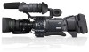
JVC GY-HD250U 117 page operator's manual for the GY-HD250U - Page 68
Connecting the Video, Signal Cables - camcorder
 |
UPC - 046838027383
View all JVC GY-HD250U manuals
Add to My Manuals
Save this manual to your list of manuals |
Page 68 highlights
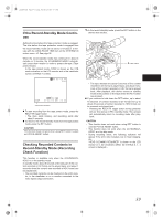
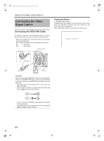
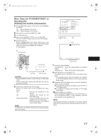
e_hd250.book Page 64 Tuesday, October 24, 2006 3:11 PM USING EXTERNAL COMPONENTS Connecting the Video Signal Cables Connecting the IEEE1394 Cable To reduce the emission of unwanted radio waves, be sure to attach the provided clamp filter as shown in the figure below. • Attach the clamp filter as close to this device as possible, as shown in the figure. • Set the IEEE1394 switch on the left panel of this device. DV HDV : DV format : HDV format IEEE1394 switch Clamp filter Displaying Alarms • CHANGE 1394 SWITCH Displayed when the setting for the input/output video format from the IEEE1394 connector and the setting for the IEEE1394 switch are different. Set the IEEE1394 switch so it matches the video format. CHANGE 1394 SWITCH Wind once CH2-AUDIO OUT-CH1 VIDEO IEEE 1394 CAUTION When connecting the IEEE1394 cable from/to Camcorder, VCR and other IEEE1394 device, make sure the following instructions, otherwise the IEEE1394 circuit device may be destroyed. • Turn the power of both devices OFF and connect the IEEE1394 cable. • Do not insert incorrectly (in reverse) the IEEE1394 cable end to IEEE1394 port of both devices. X • Do not connect the IEEE1394 cable under the condition of static electricity. • Turn the power of both devices OFF when changing the IEEE1394 switch from/to HDV/DV. IEEE 1394 IEEE 1394 64
-
 1
1 -
2
-
3
-
4
-
5
-
6
-
7
-
8
-
9
-
10
-
11
-
12
-
13
-
14
-
15
-
16
-
17
-
18
-
19
-
20
-
21
-
22
-
23
-
24
-
25
-
26
-
27
-
28
-
29
-
30
-
31
-
32
-
33
-
34
-
35
-
36
-
37
-
38
-
39
-
40
-
41
-
42
-
43
-
44
-
45
-
46
-
47
-
48
-
49
-
50
-
51
-
52
-
53
-
54
-
55
-
56
-
57
-
58
-
59
-
60
-
61
-
62
-
 63
63 -
 64
64 -
 65
65 -
 66
66 -
 67
67 -
 68
68 -
 69
69 -
 70
70 -
 71
71 -
 72
72 -
 73
73 -
74
-
75
-
76
-
77
-
78
-
79
-
80
-
81
-
82
-
83
-
84
-
85
-
86
-
87
-
88
-
89
-
90
-
91
-
92
-
93
-
94
-
95
-
96
-
97
-
98
-
99
-
100
-
101
-
102
-
103
-
104
-
105
-
106
-
107
-
108
-
109
-
110
-
111
-
112
-
113
-
114
-
115
-
116
-
117
 |
 |
