JVC GY-HD250U 117 page operator's manual for the GY-HD250U - Page 29
Status 1
 |
UPC - 046838027383
View all JVC GY-HD250U manuals
Add to My Manuals
Save this manual to your list of manuals |
Page 29 highlights
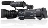
e_hd250.book Page 25 Tuesday, October 24, 2006 3:11 PM 1 3 2 4 External Image Input Mode (AUX IN) c 2 DV-60I AUX 4 8 a 5 5 0 97 6b STATUS 1 Screen 7 6b STATUS 1 Screen STATUS 1 In addition to the information on the STATUS 0 screen, this screen displays the following items. No. Item Contents 1 VIDEO FORMAT display Displays the currently selected video format. Allows you to select the REC item on the VIDEO FORMAT[1/2] menu screen. X See page 77. You can switch this display ON/OFF using the VIDEO FORMAT item on the LCD/VF[3/4] menu screen. X See page 91. 2 Time Code (TC)/User's Bits Indicates the time code (h:m:s:frame) or user's bits data. (UB) indication (Example) Time code TC 00 : 00 : 00 : 00 Colon (:) when non-drop frame mode Dot (.) when drop frame mode User's bits UB FF EE DD 20 Whether or not to display this item is set with the TC/UB item on the LCD/VF[3/4] menu screen. X See page 91. Whether the time code or user's bits should be shown is selected with the TC DISPLAY switch inside the LCD door. 3 Synchronized display with an Lights up when the time code generator of this device synchronizes with the time code input from the TC external time code generator IN terminal. Blinks when synchronization is unsuccessful. Turns off If there is no input signal. 4 Remaining tape indication Remaining tape indication (displayed in 1-minute steps) This indicator blinks when remaining tape time is equivalent to less than 3 minutes. Whether or not to display this item is set with the TAPE REMAIN item on the LCD/VF[3/4] menu screen. X See page 91. * When inserting a brand-new tape, the remaining tape time is not indicated. When the tape has been run, the indication will appear. * The remaining tape indication is to be regarded only as a guide. * When this device is used at low temperatures, it may take a while before the indication of the remaining tape time appears. 5 Voltage indication (Example) 12.2V: Indicates remaining battery level in 0.1V steps. Battery voltage and remaining battery are displayed. Select the display method in BATTERY INFO. on the LCD/VF[3/4] menu screen. X See page 91. Anton Bauer battery: Voltage/remaining capacity (%)/remaining time IDX Endura battery : Voltage/remaining capacity (%) 25
-
 1
1 -
2
-
3
-
4
-
5
-
6
-
7
-
8
-
9
-
10
-
11
-
12
-
13
-
14
-
15
-
16
-
17
-
18
-
19
-
20
-
21
-
22
-
23
-
 24
24 -
 25
25 -
 26
26 -
 27
27 -
 28
28 -
 29
29 -
 30
30 -
 31
31 -
 32
32 -
 33
33 -
 34
34 -
35
-
36
-
37
-
38
-
39
-
40
-
41
-
42
-
43
-
44
-
45
-
46
-
47
-
48
-
49
-
50
-
51
-
52
-
53
-
54
-
55
-
56
-
57
-
58
-
59
-
60
-
61
-
62
-
63
-
64
-
65
-
66
-
67
-
68
-
69
-
70
-
71
-
72
-
73
-
74
-
75
-
76
-
77
-
78
-
79
-
80
-
81
-
82
-
83
-
84
-
85
-
86
-
87
-
88
-
89
-
90
-
91
-
92
-
93
-
94
-
95
-
96
-
97
-
98
-
99
-
100
-
101
-
102
-
103
-
104
-
105
-
106
-
107
-
108
-
109
-
110
-
111
-
112
-
113
-
114
-
115
-
116
-
117
 |
 |
