JVC KY-F550U Instruction Manual
JVC KY-F550U - 3-ccd Color Camera Manual
 |
View all JVC KY-F550U manuals
Add to My Manuals
Save this manual to your list of manuals |
JVC KY-F550U manual content summary:
- JVC KY-F550U | Instruction Manual - Page 1
purchasing this JVC product. Before operating this unit, please read the instructions carefully to ensure the best possible performance. For Customer Use: Enter below the Serial No. which is located on the bottom of cabinet. Retain this information for future reference. Model No. KY-F550U Serial - JVC KY-F550U | Instruction Manual - Page 2
Thank you for purchasing the JVC KY-F550 Color Video Camera. These instructions are for KY-F550U. SAFETY PRECAUTIONS FOR USA AND CANADA This symbol indicates type B equipment classified in accordance with IEC Publication. 60601-1 Safety of medical electrical equipment. The use - JVC KY-F550U | Instruction Manual - Page 3
to use for non Medical usage. Please use for appropriate AC Adaptor for your system. JVC Sales Office JVC PROFESSIONAL PRODUCTS COMPANY 1700 VALLEY ROAD, WAYNE, NJ 07470, U.S.A. TEL : (973)315-5000 JVC CANADA INC. 21 FINCHDENE SQUARE, SCARBOROUGH, ONTARIO M1X 1A7, CANADA TEL : (416)293-1311 II - JVC KY-F550U | Instruction Manual - Page 4
service personnel under the following conditions: a. When the power cord or plug is damaged or frayed. b. If liquid has been spilled into the appliance. c. If the appliance has been exposed to rain or water. d. If the appliance does not operate normally by following the operating instructions - JVC KY-F550U | Instruction Manual - Page 5
of important operating and maintenance (servicing) instructions in the literature accompanying the . CAUTION CHANGES OR MODIFICATIONS NOT APPROVED BY JVC COULD VOID USER'S AUTHORITY TO OPERATE THE EQUIPMENT . SE REFERER A UN AGENT QUALIFIE EN CAS DE PROBLEME. Le symbole de l'éclair à l'intérieur d'un - JVC KY-F550U | Instruction Manual - Page 6
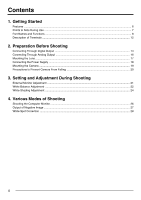
Contents 1. Getting Started Features ...6 Points to Note During Use ...7 Part Names and Functions ...8 Description of Terminals ...12 2. Preparation Before Shooting Connecting Through Digital Output ...14 Connecting Through Analog Output 16 Mounting the Lens ...17 Connecting the Power Supply ...18 - JVC KY-F550U | Instruction Manual - Page 7
...48 Connecting the analog output (D-SUB) Cable 48 Technical Information ...49 Specifications ...50 Notations and Symbols Used in This Manual Caution Note ☞ Precautions during operation are stated. Restrictions of functions and specifications are stated for reference purposes. Indicates the - JVC KY-F550U | Instruction Manual - Page 8
Feature Still images (frozen images) of the camera can be captured with triggering input timing. ● Built-in White Spot Correction Feature ● Equipped with Remote Terminal Supports remote control via the remote control unit (sold separately). 6 - JVC KY-F550U | Instruction Manual - Page 9
Points to Note During Use ● For important shootings, perform trials in advance to ensure that they are properly recorded. ● We will not compensate for contents lost due to the malfunction of this unit. Ⅵ Characteristic CCD Phenomena ● Smear and Blooming When shooting a bright light source, the CCD - JVC KY-F550U | Instruction Manual - Page 10
1. Getting Started (continued) Part Names and Functions Front / Bottom 4 1 2 3 1 Lens Mount For mounting lens. Suitable for C mount lens meant for 3 CCDs. ☞ Page 17 'Mounting the Lens' 2 Camera Mounting Bracket Supplied together with this unit. Mount it to the top or bottom surface according to - JVC KY-F550U | Instruction Manual - Page 11
Part Names and Functions (continued) Side 576 5 / BARS MENU SET ∞ / AW 1 2 34 8 5 [MENU] Menu Button Press this button for 1-2 seconds. Menu screen will be output from the various output terminals. Press the button for 1-2 seconds again to clear the menu screen. ☞ Page 32 'Setting Procedures' - JVC KY-F550U | Instruction Manual - Page 12
1. Getting Started (continued) Part Names and Functions (continued) 9 5 / BARS MENU SET ∞/ AW 1 2 34 1 23 4 Up: ON Down: OFF 9 Function Setting Switch Use for setting the functions of this unit. Select the switches when the unit is at power off condition. ● Switch 1 [ON] : - JVC KY-F550U | Instruction Manual - Page 13
and Functions (continued) Back 10 11 17 RGB, Y/C, SYNC OUT LENS VIDEO OUT TRGGER DV POWER DC IN 12 13 REMORT SEE INSTRUCTION MANUAL 16 15 14 0 [RGB, Y/C, SYNC OUT] Analog Output Terminal Output terminal for R/G/B, Y/C and composite video/sync signal. ☞ Page 10 '9 Function Setting Switch - JVC KY-F550U | Instruction Manual - Page 14
+ 12 V Output SERVO SEL ZOOM CONTROL FOCUS CONTROL Y SIGNAL OUT 1 Pin No. 1 2 3 4 5 Signal SI Output TRIG Input GND WEN Output NC Notes ● Please consult your JVC-authorized dealer on connection of trigger terminal. ● Ensure to use cables that are shielded. Suitable Plug: Mini DIN 5 PIN 12 - JVC KY-F550U | Instruction Manual - Page 15
Description of Terminals (continued) Analog Output Terminal (D-sub 9 PIN, Female) 5 1 Notes ● Cannot be connected to computer monitor. ● Use the function setting switches located at the side of this unit to select between RGB or Y/C output. Pin No. 1 2 3 4 5 6 7 8 9 9 6 RGB Output GND GND R - JVC KY-F550U | Instruction Manual - Page 16
1 2 34 MENU SET 5 / AW [DC IN] AC Adapter REMORT SEE INSTRUCTION MANUAL [LENS] Notes ● 2 or more of this unit cannot be connected to 1 the power of this unit. 4. Set the "DV SYSTEM" under "SYSTEM" screen to "JVC". 5. Power on the computer and launch the software. 1 23 4 ON OFF Switch 1 - JVC KY-F550U | Instruction Manual - Page 17
might cause a drop in the display performance of the preview window or error might occur.) For latest information, please check the following homepage. http: //www.jvc-victor.co.jp/english/pro/prodv/download/index.html For details, please consult your - JVC KY-F550U | Instruction Manual - Page 18
' (Page 18) [DC IN] [REMOTE] [TRIGGER] AA-P700 AC ADAPTER AA-P700 POWER ON OFF AC Adapter AC IN TRGGER SET REMORT SEE INSTRUCTION MANUAL RGB, Y/C, SYNC OUT LENS VC-451-2 MENU ALARM SHEET PAPER DATA CP700DSA MITSUBISHI PAPER FEED & CUT ] COPY ONLINE POWER OPEN Color Video Printer etc - JVC KY-F550U | Instruction Manual - Page 19
Mounting the Lens Follow the procedures below when mounting the auto iris lens. Refer to the 'instruction manual' for the lens as well. Camera Head Threaded Portion Mount Fastening Ring Lens 1. 2. Lock (Male) lens is to be used and iris control is to be fine-tuned, set to "MANUAL". 17 - JVC KY-F550U | Instruction Manual - Page 20
OUTPUT S(Y/C) OUTPUT TO CAMERA RGB, Y/C, SYNC OUT DV LENS VIDEO OUT TRGGER POWER DC IN EITHER OUTPUT MAX 1.25A SEE INSTRUCTION MANUAL REMORT SEE INSTRUCTION MANUAL White Marking [TO CAMERA] Terminal [DC IN] Terminal Connect the end with white marking to the AC adaptor. Power Cable - JVC KY-F550U | Instruction Manual - Page 21
Mounting the Camera Use the supplied camera mounting bracket and 2 fastening screws of the camera mounting bracket to mount it to the top or bottom surface. Caution Make sure to use screws that are supplied with this unit. Use of screws that are 6 mm - JVC KY-F550U | Instruction Manual - Page 22
2. Preparation Before Shooting (continued) Precautions to Prevent Camera From Falling Safety cable to Prevent Falling of Equipment 4 mm 1-1.5 mm Camera Head Caution ● Special attention is required when mounting to the wall or ceiling. Get a contractor to perform the work and avoid doing it on your - JVC KY-F550U | Instruction Manual - Page 23
to adjust color bars 3 and 0, 5 and @ to the same brightness level. 6. If brightness of color bars 1 and 8, 7 and $ vary upon REMORT SEE INSTRUCTION MANUAL [PHASE] adjustment, repeat chroma adjustment as in step 4.. 7. Turn [BLUE CHECK] at the monitor to OFF and return to the normal screen - JVC KY-F550U | Instruction Manual - Page 24
WH I TE 1 O PERA T I O N Auto White Operation Activated AUTO W H I TE 1 OK (3200K) White balance adjustment includes Auto White, Full-time Auto White (FAW), manual and preset. Ⅵ Setting procedures for Auto White ("AUTO1", "AUTO2") Make sure that the Switch 4 located at the side of this unit is set - JVC KY-F550U | Instruction Manual - Page 25
White Balance Adjustment (continued) AUTO WH ITE 1 NG : OB J ECT Object Error AUTO WH ITE 1 ERROR : LOW L I GH T Insufficient Illumination AUTO WH ITE 1 ERROR : OV ER L I GHT Excessive Illumination Error Display When auto white adjustment is not correctly ended, the following message will be - JVC KY-F550U | Instruction Manual - Page 26
3. Setting and Adjustment During Shooting (continued) White Shading Adjustment There are cases when white balance is achieved for the center of the screen but not for the upper and lower ends, hence causing other colors to appear with green or magenta. This is brought about by the lens - JVC KY-F550U | Instruction Manual - Page 27
White Shading Adjustment (continued) AUT O SHADING OPERATION 6. Press the [AW] (Auto White) button for 1-2 seconds. ● When auto shading is activated, "AUTO SHADING OPERATION" is displayed on the monitor. ● When auto shading adjustment is achieved, "AUTO SHADING OK" will be displayed for about 3 - JVC KY-F550U | Instruction Manual - Page 28
4. Various Modes of Shooting Shooting the Computer Monitor When shooting images of computer monitors or displays, horizontal bands will appear on the screen. To eliminate the bands, it will be necessary to align the shutter speed with the scanning frequency of the monitor. Computer Monitor 3. 4. - JVC KY-F550U | Instruction Manual - Page 29
[OFF] Blinking - - - SYSTEM - - - NEGA T I VE SETUP P I XE L COMPEN DV SYSTEM PAGE BACK OF F ON CANCE L JVC "SYSTEM" Screen 4. 5. - - - SYSTEM - - - NEGA T I VE SETUP P I XE L COMPEN DV SYSTEM PAGE BACK ON ON CANCE L JVC Make sure that the Switch 4 located at the side of this unit is set to - JVC KY-F550U | Instruction Manual - Page 30
lens cap to prevent light from entering the CCD.) 2. 3. Blinking Operation - - - SYSTEM - - - NEGA T I VE SETUP P I XE L COMPEN DV SYSTEM PAGE BACK OFF ON CANCE L JVC "SYSTEM" Screen 4. 5. Blinking - - - SYSTEM - - - NEGA T I VE SETUP P I XE L COMPEN DV SYSTEM PAGE BACK OFF ON EXECUTE - JVC KY-F550U | Instruction Manual - Page 31
performed depending on the nature of the white spots. In such case, perform the detection again until white spots are detected. Consult your JVC authorized dealer if white spots cannot be corrected. Quantity of Detection/Correction: 32 or less ● The screen on the right may be displayed - JVC KY-F550U | Instruction Manual - Page 32
KNEE AUTO LEVEL NEXT PAGE . . PAGE BACK - - - - - - ☞ Page 38 - - - SYSTEM - - - NEGA T I VE OFF SETUP P I XE L COMPEN ON CANCE L DV SYSTEM JVC PAGE BACK ☞ Page 41 ☞ Page 44 - - - F I LE MANAGE - - - LOAD F I LE LOAD STORE F I LE S TORE RESET F I LE RESET PAGE BACK A CANCE L A CANCE - JVC KY-F550U | Instruction Manual - Page 33
Flow of Menu Screens (continued) - - - ADVANCED EXPOSURE - - - ALC L I M I T EE I L I M I T AE LEVE L AE DETECT AE AREA . . PAGE BACK +18 dB 1 /240 0 NORMAL ☞ Page 35 ● At any displayed screen, normal screen will be restored if [MENU] button is pressed for 1-2 seconds. ● When the remote control - JVC KY-F550U | Instruction Manual - Page 34
5. Setting Via the Menu Screen (continued) Setting Procedures The various functions of this unit can be set using the menu screen. Settings will be stored in the memory of this unit and will remain recorded when the power is turned off. [MENU] [5] [SET] 5/ BARS MENU SET ∞/ AW 1 2 34 [∞] - JVC KY-F550U | Instruction Manual - Page 35
Increase value : Opens the iris. Decrease value : Closes iris. {Variable Values : 0 - 128 - 255} Note When "IRIS MODE" is set to "AUTO", "MANUAL LEVEL" item selection will be disabled. (Displayed as For switching the electric sensitivity mode. "STEP" : Gain boost level can be altered using - JVC KY-F550U | Instruction Manual - Page 36
auto white, auto iris, "ALC" and "FAW" will be as follows: Auto White : Startup of auto white is disabled. Auto Iris : Change to "MANUAL". "ALC" : Change to "STEP (0 dB)". "FAW" : Change to "AUTO1". ● There will be insufficient light intensity if the shutter speed is increased and adjustment - JVC KY-F550U | Instruction Manual - Page 37
"ADVANCED EXPOSURE" Screen Settings in bold are factory settings Item "ALC LIMIT" "EEI LIMIT" "AE LEVEL" "AE DETECT" "AE AREA.." Function/Variable Values For setting the maximum "ALC" value that triggers automatic switching of gain boost level according to the brightness. {Variable Values : - JVC KY-F550U | Instruction Manual - Page 38
tuning of white color upon achieving white balance. "FAW" : Automatic adjustment of white balance according to different illumination conditions. "MANUAL" : Manual adjustment of white balance. Can be altered using the "LEVEL (R)" and "LEVEL (B)" items. "PRESET" : Fixes white balance at 3200 - JVC KY-F550U | Instruction Manual - Page 39
end of screen. {Variable Values: -128 - 0 - +127} For adjusting bluishness of white shading only when the "SHADING" item is set to "MANUAL". Increase value : Decreases bluishness at lower end and increases bluishness at upper end of screen. Decrease value : Decreases bluishness at upper end - JVC KY-F550U | Instruction Manual - Page 40
5. Setting Via the Menu Screen (continued) "PROCESS (1/2)" Screen Settings in bold are factory settings Item "MASTER BLACK" "DETAIL" "LEVEL" "V/H BALANCE" "FREQUENCY" "V. RESOLUTION" Function/Variable Values For adjusting the pedestal level (master black), which is based on the black color - JVC KY-F550U | Instruction Manual - Page 41
under "EXPOSURE" screen is set to "SLOW" or when the "MODE" item under "CAPTURE" screen is set to "RANDOM TRG", it will change to "MANUAL". Press the [SET] button to invoke the "PROCESS(2/2)" screen when the cursor is at this position. ☞ Page 40 'PROCESS (2/2) Screen' Press the [SET] button - JVC KY-F550U | Instruction Manual - Page 42
42 'MATRIX ADJUST Screen' For adjusting the gamma curve that determines the reproducibility of black color. "OFF" : Disables gamma curve adjustment. "MANUAL" : Amount of gamma curve adjustment can be altered using the "LEVEL" item. Gamma curve adjustment is enabled only when the "GAMMA" item - JVC KY-F550U | Instruction Manual - Page 43
correction. ☞ Page 28 'White Spot Correction' For setting the software to be used for remote-controlling this unit via the [DV] terminal. "JVC" : When using the exclusive software of this unit. "OTHERS" : When using software other than the exclusive software. (Setting of '9 Function Setting - JVC KY-F550U | Instruction Manual - Page 44
R axis of the color matrix (red and cyan). Increase value : Enhances red and cyan. Decrease value : Reduces red and cyan. {Variable Values : -3 - 0 - +3} For manually adjusting the color phase of the R axis of the color matrix (red and cyan). Increase value : Increases yellowishness of red color and - JVC KY-F550U | Instruction Manual - Page 45
"CAPTURE" Screen Settings in bold are factory settings Item "MODE" "FREEZE TRG" "IMAGE TYPE" "RANDOM SHUT. " "PAGE BACK" Function/Variable Values For capturing images into the memory and output still images (frozen images) through the various output terminals located at the back of this unit. - JVC KY-F550U | Instruction Manual - Page 46
5. Setting Via the Menu Screen (continued) "FILE MANAGE" Screen The following can be performed on the "FILE MANAGE" screen. ● Saving menu settings in 3 types of files (A, B and C). ● Retrieving stored files (A, B and C). ● Resetting menu settings to factory settings. 1. 2. - - - MENU - - - - JVC KY-F550U | Instruction Manual - Page 47
"FILE MANAGE" Screen (continued) 1. 2. Blinking - - - F I LE MANAGE - - - LOAD F I LE LOAD STORE F I LE S TORE RESET F I LE RESET PAGE BACK A CANCE L A CANCE L A CANCE L 3. 4. Blinking - - - F I LE MANAGE - - - LOAD F I LE LOAD STORE F I LE S TORE RESET F I LE RESET PAGE BACK A EXECUTE A - JVC KY-F550U | Instruction Manual - Page 48
Control Unit Menu function of the camera can be set using the remote control unit (RM-LP55 AND RM-LP57). (Please refer to the instruction manual of the remote control unit for details on remote control operations. ) RM-LP55 3. Use the [FUNC2 §/∫] buttons to set the camera RGB, Y/C, SYNC OUT - JVC KY-F550U | Instruction Manual - Page 49
RM-LP55 }⅜ ⅜ BARS, CAM, NEGA ⅜ ⅜ ⅜ ON (LEVEL), OFF ⅜ ן ⅜ ⅜ LEVEL ⅜ ⅜ AUTO (LEVEL), MANU ⅜ ⅜ NORMAL, PEAK, AVG ⅜ ⅜ AUTO1, AUTO2, FAW, MANUAL, PRESET ⅜ ⅜ AUTO1, AUTO2 ⅜ ⅜ -3, 0, 6, 9, 12, 18 dB, ALC, ALC+EEI, LOLUX ⅜ ⅜ NORMAL,1/100, 1/250, 1/500, 1/1000,1/2000, V. SCAN, EEI - JVC KY-F550U | Instruction Manual - Page 50
6. Others (continued) Connecting the IEEE 1394 Cable Wind Once ● Attach the supplied clamp filter as shown in the diagram on the left to reduce unwanted electromagnetic emission. ● Attach the clamp filter as shown in the diagram on the left to this unit as near as possible. ● Set Switch 1 and - JVC KY-F550U | Instruction Manual - Page 51
1 charges Image output signal 1 1 1 WEN output signal Caution ● Normal image level cannot be used under the auto iris mode. Please use the manual iris mode. ● Noise may increase when the number of frames increases, as such, set to an appropriate value. Ⅵ Random Trigger Function For verifying - JVC KY-F550U | Instruction Manual - Page 52
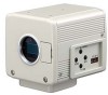
6. Others (continued) Specifications Image Pickup Device : 1/3" IT CCD x 3 Scan Mode : Interlace Effective Pixel Numbers : 380,000 Pixels (768 (H) x 494 (V)) Lens Mount : 1/3" C Mount Color Separation System : F1.4 3-color Separation Prism Aspect Ratio : 4:3 Horizontal Resolution : Y: - JVC KY-F550U | Instruction Manual - Page 53
: Power Cord (8P, 2 m) x 1 Camera Mounting Bracket x 1 Camera Mounting Bracket Fastening Screw (M2.6 x 6 mm) x 2 Clamp Filter x 2 Wire Clamp x 2 Instruction Manual x 1 Dimensional Drawing (Unit: mm) 67.5 66 WARNING: NEVER ATTACH A LENS WHICH PROTRUDES MORE THAN 4mm SEVERE DAMAGE WILL RESULT - JVC KY-F550U | Instruction Manual - Page 54
Memo ...52 - JVC KY-F550U | Instruction Manual - Page 55
...53 - JVC KY-F550U | Instruction Manual - Page 56
® is a registered trademark owned by Victor Company of Japan, Limited. ® is a registered trademark in Japan, the U.S.A., the U.K. and many other countries. © 2004 Victor Company of Japan, Limited Printed in Japan LWT0158-001B COLOR VIDEO CAMERA KY-F550
-
 1
1 -
 2
2 -
 3
3 -
 4
4 -
 5
5 -
 6
6 -
 7
7 -
8
-
9
-
10
-
11
-
12
-
13
-
14
-
15
-
16
-
17
-
18
-
19
-
20
-
21
-
22
-
23
-
24
-
25
-
26
-
27
-
28
-
29
-
30
-
31
-
32
-
33
-
34
-
35
-
36
-
37
-
38
-
39
-
40
-
41
-
42
-
43
-
44
-
45
-
46
-
47
-
48
-
49
-
50
-
51
-
52
-
53
-
54
-
55
-
56
 |
 |
KY-F550
COLOR VIDEO CAMERA
INSTRUCTIONS
For Customer Use:
Enter below the Serial No. which is
located on the bottom of cabinet. Retain
this information for future reference.
Model No.
KY-F550U
Serial No.
Thank you for purchasing this JVC product.
Before operating this unit, please read the
instructions carefully to ensure the best
possible performance.
This instruction manual is made from 100%
recycled paper.
*Illustration with optional lens attachment.
LWT0158-001B