JVC KY-F550U Instruction Manual - Page 18
Connecting Through Analog Output
 |
View all JVC KY-F550U manuals
Add to My Manuals
Save this manual to your list of manuals |
Page 18 highlights
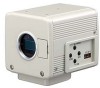
2. Preparation Before Shooting (continued) Connecting Through Analog Output Images taken by this unit can be output to monitor, color video printer or other devices. Monitor BNC CABLE [VIDEO OUT] Clamp filter (accessories) DV [RGB, Y/C, SYNC OUT] VIDEO OUT POWER DC IN 'Connecting the Power Supply' (Page 18) [DC IN] [REMOTE] [TRIGGER] AA-P700 AC ADAPTER AA-P700 POWER ON OFF AC Adapter AC IN TRGGER SET REMORT SEE INSTRUCTION MANUAL RGB, Y/C, SYNC OUT LENS VC-451-2 MENU ALARM SHEET PAPER DATA CP700DSA MITSUBISHI PAPER FEED & CUT ] COPY ONLINE POWER OPEN Color Video Printer etc. R G/Y B/C SYNC VBS Microscope Adapter Trigger Switch REMOTE CONTROL UNIT RM-LP55 RM-LP57 1. Connect device such as the Color Video Printer to this unit's [RGB, Y/C, SYNC OUT] terminal. 2. Set the switches located at the side of this unit. ● Setting Switch 2 Set this switch to [ON] (upper side) for Y/C output. Set this switch to [OFF] (lower side) for RGB output. ● Setting Switch 3 Set this switch to [ON] (upper side) if sync signal is to be superimposed onto the Green (G) channel of the video signal. ☞ Page 10 '9 Function Setting Switch' Example: During RGB output 1 23 4 ON OFF Switch 2 Switch 3 3. Switch on the power of this unit. Caution ● Perform this when the devices are off. ● Use the 1/3-inch, C mount adapter for the micro- scope adapter. Notes ● Connect a switch between PIN 2 (TRIG) and PIN 3 (GND) of the [TRIGGER] terminal. If this switch is set to [ON], a trigger will freeze the input image to the camera and capturing of images synchronized with the trigger is possible. ● Ensure to attach the supplied clamp filter to the cable connected to the Analog Signal Output [RGB, Y/C, SYNC OUT] terminal in order to reduce unwanted electromagnetic emissions. ☞ Page 48 16
-
 1
1 -
2
-
3
-
4
-
5
-
6
-
7
-
8
-
9
-
10
-
11
-
12
-
 13
13 -
 14
14 -
 15
15 -
 16
16 -
 17
17 -
 18
18 -
 19
19 -
 20
20 -
 21
21 -
 22
22 -
 23
23 -
24
-
25
-
26
-
27
-
28
-
29
-
30
-
31
-
32
-
33
-
34
-
35
-
36
-
37
-
38
-
39
-
40
-
41
-
42
-
43
-
44
-
45
-
46
-
47
-
48
-
49
-
50
-
51
-
52
-
53
-
54
-
55
-
56
 |
 |
