JVC KY-F550U Instruction Manual - Page 12
Function Setting Switch, Switch 3 <SYNC ON GREEN>
 |
View all JVC KY-F550U manuals
Add to My Manuals
Save this manual to your list of manuals |
Page 12 highlights
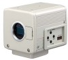
1. Getting Started (continued) Part Names and Functions (continued) 9 5 / BARS MENU SET ∞/ AW 1 2 34 1 23 4 Up: ON Down: OFF 9 Function Setting Switch Use for setting the functions of this unit. Select the switches when the unit is at power off condition. ● Switch 1 [ON] : Compressed DV signal (IEEE1394) of the camera images will be output. [OFF] : DV signal will not be output. Note If [ON] is selected, the analog output will exhibit the same level of horizontal resolution (about 540 lines) as the DV output. ● Switch 2 [ON] : Y/C signal will be output. [OFF] : RGB signal will be output. ● Switch 3 [ON] : Sync signal will be superimposed onto the Green (G) channel of the video signal output to the [RGB, Y/ C, SYNC OUT] terminal 0. [OFF] : Sync signal will not be superimposed. ● Switch 4 [ON] : Operate the camera via [DV] terminal (IEEE1394). Operation via [MENU], [SET], [5/ BARS], [∞/AW] buttons and the remote control unit will not function. [OFF] : Operate the camera via the buttons on this unit or the remote control unit. Operation via [DV] terminal (IEEE1394) is not functional. 10
-
 1
1 -
2
-
3
-
4
-
5
-
6
-
 7
7 -
 8
8 -
 9
9 -
 10
10 -
 11
11 -
 12
12 -
 13
13 -
 14
14 -
 15
15 -
 16
16 -
 17
17 -
18
-
19
-
20
-
21
-
22
-
23
-
24
-
25
-
26
-
27
-
28
-
29
-
30
-
31
-
32
-
33
-
34
-
35
-
36
-
37
-
38
-
39
-
40
-
41
-
42
-
43
-
44
-
45
-
46
-
47
-
48
-
49
-
50
-
51
-
52
-
53
-
54
-
55
-
56
 |
 |
