Lenovo ThinkCentre M50 User Manual - Page 100
Power
 |
View all Lenovo ThinkCentre M50 manuals
Add to My Manuals
Save this manual to your list of manuals |
Page 100 highlights
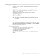
The following illustration shows the locations of parts on the system board. 1 Microprocessor 2 DIMM connector 1 3 DIMM connector 2 4 DIMM connector 3 5 DIMM connector 4 6 Power connector 7 Diskette drive connector 8 PATA primary IDE connector 9 PATA secondary IDE connector 10 SATA 1 IDE connector 11 SATA 2 IDE connector 12 Promise of value (POV) daughter card (some models) 13 Clear CMOS/Recovery jumper 14 Battery 15 SCSI LED connector 16 PCI slots 17 Front panel audio connector 18 CD-ROM audio connector 19 AGP slot Installing memory Your computer has four connectors for installing dual inline memory modules (DIMMs) that provide up to a maximum of 4.0 GB of system memory. When installing DIMMs, the following rules apply: v System memory is divided into two channels (channel A and B). DIMM connectors 1 and 2 are channel A, and DIMM connectors 3 and 4 are channel B. v If DIMM connectors 1 and 3 (or 2 and 4) are filled with the same technology and size of memory, the system operates in dual channel mode. v Use 2.5 V, 184-pin, 333 MHz double data rate synchronous dynamic random access memory (DDR SDRAM). v Use 128 MB, 256 MB, 512 MB or 1 GB (when available) DIMMs in any combination. v DIMMs are 25.4 mm (1.0 inch) in height. 84 User Guide Note: Only DDR SDRAM DIMMs can be used.
-
 1
1 -
2
-
3
-
4
-
5
-
6
-
7
-
8
-
9
-
10
-
11
-
12
-
13
-
14
-
15
-
16
-
17
-
18
-
19
-
20
-
21
-
22
-
23
-
24
-
25
-
26
-
27
-
28
-
29
-
30
-
31
-
32
-
33
-
34
-
35
-
36
-
37
-
38
-
39
-
40
-
41
-
42
-
43
-
44
-
45
-
46
-
47
-
48
-
49
-
50
-
51
-
52
-
53
-
54
-
55
-
56
-
57
-
58
-
59
-
60
-
61
-
62
-
63
-
64
-
65
-
66
-
67
-
68
-
69
-
70
-
71
-
72
-
73
-
74
-
75
-
76
-
77
-
78
-
79
-
80
-
81
-
82
-
83
-
84
-
85
-
86
-
87
-
88
-
89
-
90
-
91
-
92
-
93
-
94
-
 95
95 -
 96
96 -
 97
97 -
 98
98 -
 99
99 -
 100
100 -
 101
101 -
 102
102 -
 103
103 -
 104
104 -
 105
105 -
106
-
107
-
108
-
109
-
110
-
111
-
112
-
113
-
114
-
115
-
116
-
117
-
118
-
119
-
120
-
121
-
122
-
123
-
124
-
125
-
126
-
127
-
128
-
129
-
130
-
131
-
132
-
133
-
134
-
135
-
136
-
137
-
138
 |
 |
